Cirkit Designer
Your all-in-one circuit design IDE
Home /
Project Documentation
Rectifier Diode and LED Circuit with Rocker Switch Control
Circuit Documentation
Summary of the Circuit
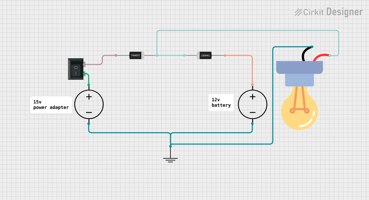
The circuit described by the provided inputs appears to be a simple power supply circuit with a switch, a protective diode, and an LED indicator. The circuit uses two DC power sources, which are likely to be connected to different voltage levels. The diodes are used to prevent reverse current flow, which could damage the circuit, while the LED indicates the presence of power. The rocker switch (SPST) is used to control the flow of current to the circuit. There is no microcontroller or embedded code involved in this circuit.
Component List
1N4007 Rectifier Diode
- Description: A general-purpose rectifier diode that can handle up to 1000V reverse voltage and 1A of forward current.
- Purpose: To prevent reverse current flow that could potentially harm the circuit.
- Pins: Cathode, Anode
DC Power Source
- Description: A source of direct current that provides electrical energy to the circuit.
- Purpose: To supply the necessary voltage and current to the circuit.
- Pins: Ground, Positive
GND (Ground)
- Description: A reference point in an electrical circuit from which voltages are measured, a common return path for electric current, or a direct physical connection to the Earth.
- Purpose: To serve as a common return path for electric current and to stabilize the voltage levels in the circuit.
- Pins: GND
Rocker Switch (SPST)
- Description: A single pole single throw (SPST) switch that can connect or disconnect the circuit.
- Purpose: To allow the user to manually control the power to the circuit.
- Pins: 1, 2
LED bulb AC / Bombillo AC
- Description: A light-emitting diode (LED) that emits light when a current flows through it.
- Purpose: To indicate the presence of power in the circuit.
- Pins: +, -
Comment
- Description: A placeholder for additional information or notes about the circuit.
- Purpose: To provide extra information or context that can be useful during the circuit analysis or troubleshooting.
- Pins: None
Wiring Details
1N4007 Rectifier Diode
- Cathode is connected to:
- Cathode of another 1N4007 Rectifier Diode
- Positive pin of the LED bulb AC / Bombillo AC
- Anode is connected to:
- Pin 1 of the Rocker Switch (SPST)
- Positive pin of a DC Power Source
DC Power Source
- Ground is connected to:
- Negative pin of the LED bulb AC / Bombillo AC
- GND pin of the GND component
- Positive is connected to:
- Pin 2 of the Rocker Switch (SPST)
- Anode of a 1N4007 Rectifier Diode
GND (Ground)
- GND is connected to:
- Ground pin of the DC Power Source
- Negative pin of the LED bulb AC / Bombillo AC
Rocker Switch (SPST)
- Pin 1 is connected to:
- Anode of a 1N4007 Rectifier Diode
- Pin 2 is connected to:
- Positive pin of a DC Power Source
LED bulb AC / Bombillo AC
- + (Positive) is connected to:
- Cathode of the 1N4007 Rectifier Diode
- - (Negative) is connected to:
- Ground pin of the DC Power Source
- GND pin of the GND component
Documented Code
There is no embedded code provided for this circuit as it does not include any programmable components such as microcontrollers.