
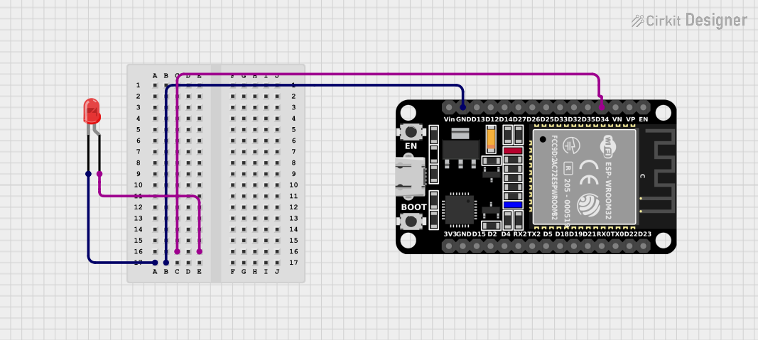
Circuit Documentation
Summary
This circuit consists of an ESP32 microcontroller and a red LED. The ESP32 controls the LED, making it blink at regular intervals. The LED's anode is connected to one of the GPIO pins of the ESP32, while the cathode is connected to the ground (GND) pin of the ESP32.
Component List
LED: Two Pin (red)
- Description: A standard red LED with two pins: anode and cathode.
- Pins:
- anode
- cathode
ESP32 (30 pin)
- Description: A versatile microcontroller with 30 pins, including GPIO, power, and communication pins.
- Pins:
- EN
- VP
- VN
- D34
- D35
- D32
- D33
- D25
- D26
- D27
- D14
- D12
- D13
- GND
- Vin
- D23
- D22
- TX0
- RX0
- D21
- D19
- D18
- D5
- TX2
- RX2
- D4
- D2
- D15
- 3V3
Wiring Details
LED: Two Pin (red)
- anode is connected to D34 of the ESP32.
- cathode is connected to GND of the ESP32.
ESP32 (30 pin)
- D34 is connected to the anode of the LED.
- GND is connected to the cathode of the LED.
Code Documentation
ESP32 Code
int led = 34;

void setup() {
  // put your setup code here, to run once:
  pinMode(led, OUTPUT);
}

void loop() {
  // put your main code here, to run repeatedly:
  digitalWrite(led, HIGH);
  delay(500);
  digitalWrite(led, LOW);
  delay(500);
}
This code initializes pin D34 as an output and toggles it between HIGH and LOW states with a delay of 500 milliseconds, causing the LED to blink on and off at a 1-second interval.