
Battery-Powered LED Control Circuit with Push Switches and Relay
View and Edit Project In Cirkit Designer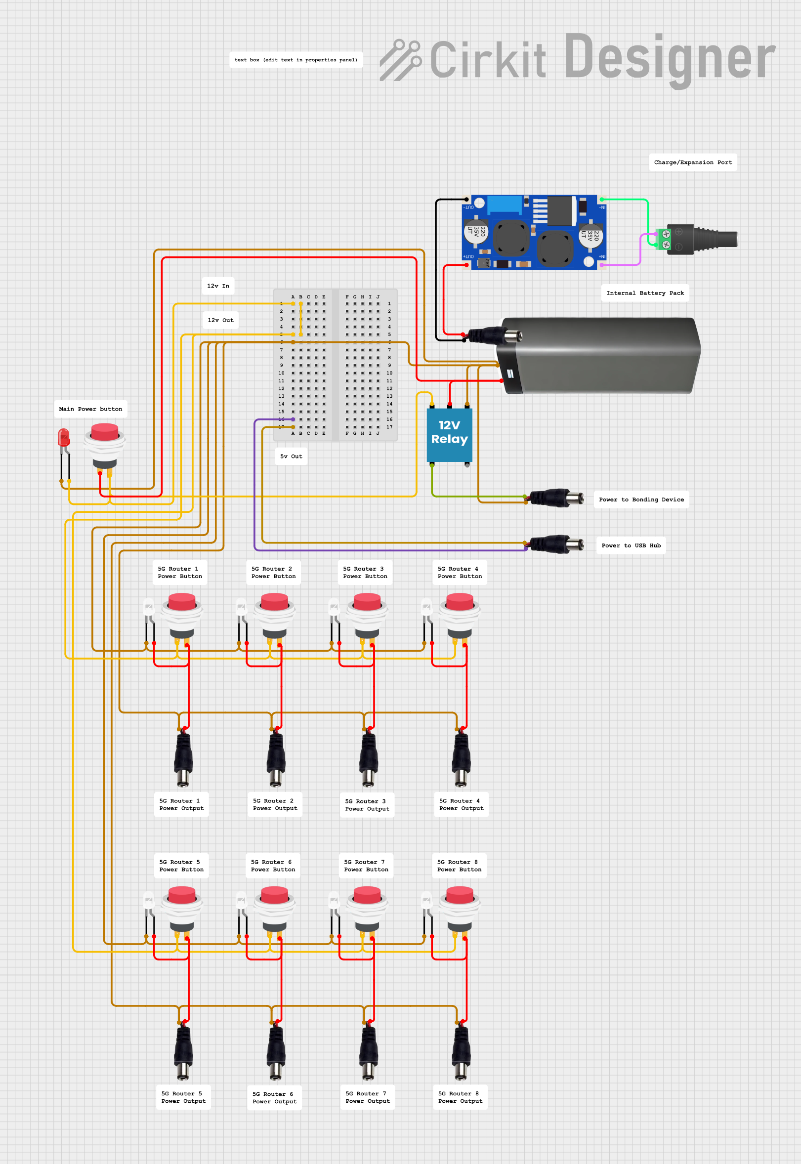
Circuit Documentation
Summary
This circuit consists of multiple LEDs, push switches, power jacks, a battery pack, a boost converter, and a relay. The circuit is designed to control the LEDs using push switches and a relay, powered by a battery pack and power jacks. The boost converter is used to step up the voltage as required.
Component List
LED: Two Pin (red)
- Pins: cathode, anode
- Description: A red LED used for visual indication.
LED: Two Pin (white)
- Pins: cathode, anode
- Description: A white LED used for visual indication.
2Pin Push Switch
- Pins: Input +, Output +
- Description: A push switch used to control the flow of current.
Power Jack
- Pins: POSITIF, NEGATIF
- Description: A power jack used to connect the power supply.
Battery Pack
- Pins: +, -
- Description: A battery pack used to provide power to the circuit.
2.1mm Barrel Jack with Terminal Block
- Pins: POS, NEG
- Description: A barrel jack used to connect external power sources.
XL6009E1 Boost Converter
- Pins: IN+, IN-, OUT+, OUT-
- Description: A boost converter used to step up the voltage.
12V Relay
- Pins: +, -, C, NC, NO
- Description: A relay used to control high-power devices.
Wiring Details
LED: Two Pin (red)
Anode is connected to:
- Output + of a 2Pin Push Switch
- Input + of multiple 2Pin Push Switches
-
- pin of the 12V Relay
Cathode is connected to:
- NEGATIF pin of multiple Power Jacks
LED: Two Pin (white)
Anode is connected to:
- Output + of multiple 2Pin Push Switches
- POSITIF pin of multiple Power Jacks
Cathode is connected to:
- NEGATIF pin of multiple Power Jacks
2Pin Push Switch
Input + is connected to:
- Output + of another 2Pin Push Switch
- Anode of the red LED
-
- pin of the Battery Pack
- C pin of the 12V Relay
Output + is connected to:
- Anode of multiple white LEDs
- POSITIF pin of multiple Power Jacks
Power Jack
POSITIF is connected to:
- Anode of multiple white LEDs
- Output + of multiple 2Pin Push Switches
- OUT+ pin of the XL6009E1 Boost Converter
- NC pin of the 12V Relay
NEGATIF is connected to:
- Cathode of multiple white LEDs
- Cathode of the red LED
- OUT- pin of the XL6009E1 Boost Converter
Battery Pack
+ is connected to:
- Input + of a 2Pin Push Switch
- C pin of the 12V Relay
- is connected to:
- Cathode of multiple white LEDs
2.1mm Barrel Jack with Terminal Block
POS is connected to:
- IN+ pin of the XL6009E1 Boost Converter
NEG is connected to:
- IN- pin of the XL6009E1 Boost Converter
XL6009E1 Boost Converter
IN+ is connected to:
- POS pin of the 2.1mm Barrel Jack with Terminal Block
IN- is connected to:
- NEG pin of the 2.1mm Barrel Jack with Terminal Block
OUT+ is connected to:
- POSITIF pin of a Power Jack
OUT- is connected to:
- NEGATIF pin of a Power Jack
12V Relay
+ is connected to:
- Output + of a 2Pin Push Switch
- is connected to:
- NEGATIF pin of multiple Power Jacks
C is connected to:
-
- pin of the Battery Pack
- Input + of a 2Pin Push Switch
-
NC is connected to:
- POSITIF pin of a Power Jack
Code
No microcontroller code is provided for this circuit.