
ESP8266 NodeMCU Based Temperature Monitoring System with LCD Display and Fan Control
View and Edit Project In Cirkit Designer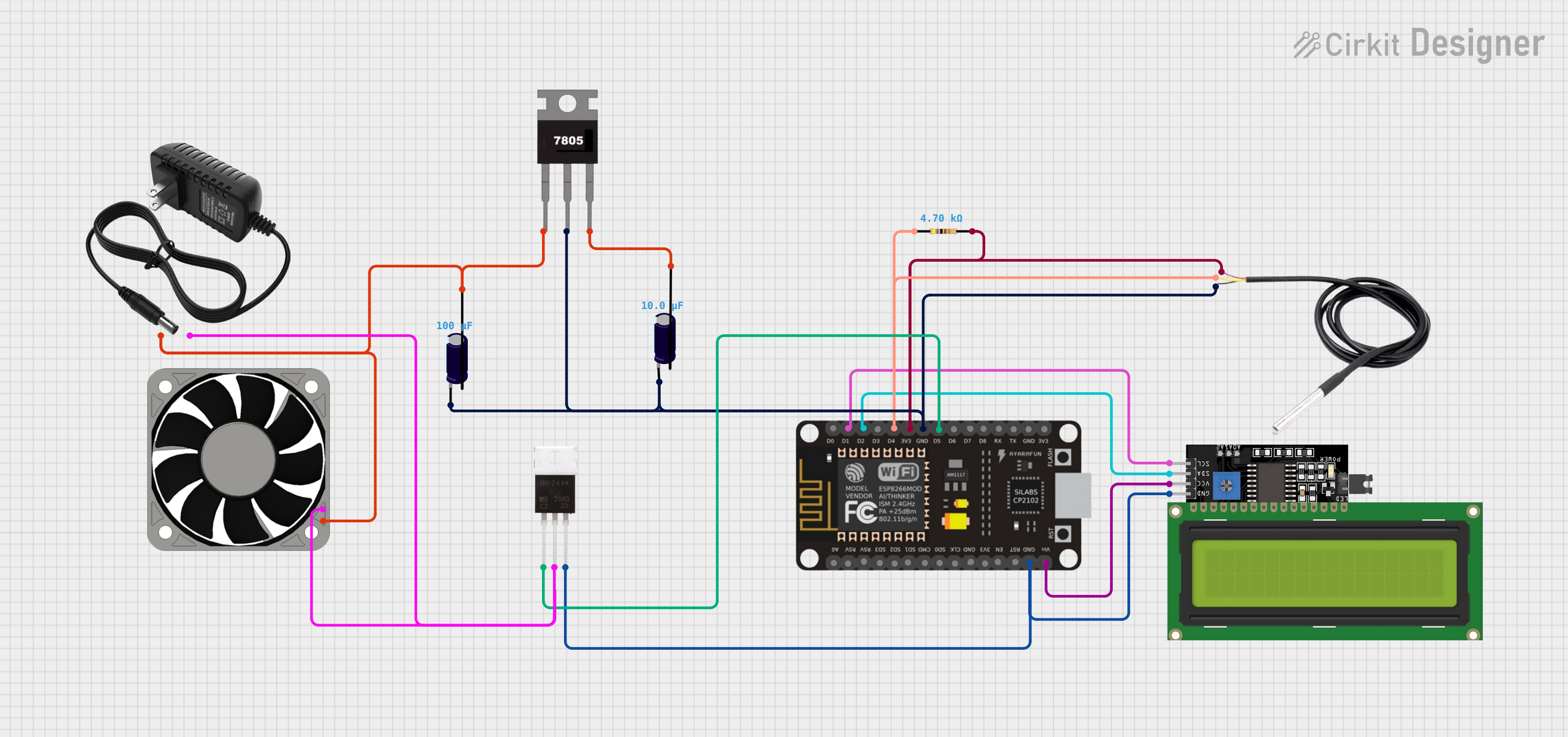
Circuit Documentation
Summary
This circuit is designed to interface an ESP8266 NodeMCU microcontroller with several peripheral devices, including a DS18B20 temperature sensor, an LCD Display (16x4 characters) with I2C interface, an IRFZ44N power MOSFET for controlling a 12V fan, and a 7805 voltage regulator for stabilizing the input voltage. The circuit also includes electrolytic capacitors for voltage smoothing and a resistor for the DS18B20 sensor. The power supply is a 12V source that powers the fan and the voltage regulator. The ESP8266 NodeMCU controls the temperature sensor, the LCD display, and the fan via the MOSFET.
Component List
ESP8266 NodeMCU
- Microcontroller with WiFi capability
- Pins: D0, D1, D2, D3, D4, 3V3, GND, D5, D6, D7, D8, RX, TX, A0, RSV, SD3, SD2, SD1, CMD, SD0, CLK, EN, RST, VIN
DS18B20
- Digital temperature sensor
- Pins: signal, GND, vcc
Resistor
- Resistance: 4700 Ohms
- Pins: pin1, pin2
IRFZ44N
- Power MOSFET
- Pins: Gate, Drain, Source
LCD Display 16x4 I2C
- Alphanumeric LCD display with I2C interface
- Pins: SCL, SDA, VCC, GND
7805
- Voltage regulator
- Pins: Vin, Gnd, Vout
Electrolytic Capacitor (10 µF)
- Capacitance: 0.00001 Farads
- Pins: -, +
Electrolytic Capacitor (100 µF)
- Capacitance: 0.0001 Farads
- Pins: -, +
40mm Fan 12V
- Cooling fan
- Pins: +12V, -12V
12V Power Supply
- Provides power to the circuit
- Pins: +, -
Wiring Details
ESP8266 NodeMCU
- D4 connected to Resistor (pin1) and DS18B20 (signal)
- 3V3 connected to Resistor (pin2) and DS18B20 (vcc)
- GND connected to Electrolytic Capacitor (10 µF, -), 7805 (Gnd), DS18B20 (GND), Electrolytic Capacitor (100 µF, -), IRFZ44N (Source), and LCD Display (GND)
- D1 connected to LCD Display (SCL)
- D2 connected to LCD Display (SDA)
- D5 connected to IRFZ44N (Gate)
- VIN connected to LCD Display (VCC)
DS18B20
- Signal connected to ESP8266 NodeMCU (D4) and Resistor (pin1)
- VCC connected to ESP8266 NodeMCU (3V3) and Resistor (pin2)
- GND connected to ESP8266 NodeMCU (GND)
Resistor (4.7k Ohms)
- Pin1 connected to ESP8266 NodeMCU (D4) and DS18B20 (signal)
- Pin2 connected to ESP8266 NodeMCU (3V3) and DS18B20 (vcc)
IRFZ44N
- Gate connected to ESP8266 NodeMCU (D5)
- Drain connected to 12V Power Supply (-) and 40mm Fan 12V (-12V)
- Source connected to ESP8266 NodeMCU (GND)
LCD Display 16x4 I2C
- SCL connected to ESP8266 NodeMCU (D1)
- SDA connected to ESP8266 NodeMCU (D2)
- VCC connected to ESP8266 NodeMCU (VIN)
- GND connected to ESP8266 NodeMCU (GND)
7805
- Vin connected to Electrolytic Capacitor (100 µF, +), 12V Power Supply (+), and 40mm Fan 12V (+12V)
- Gnd connected to ESP8266 NodeMCU (GND)
- Vout connected to Electrolytic Capacitor (100 µF, +)
Electrolytic Capacitor (10 µF)
-
- (Negative) connected to ESP8266 NodeMCU (GND)
-
- (Positive) connected to 12V Power Supply (+), 7805 (Vin), and 40mm Fan 12V (+12V)
Electrolytic Capacitor (100 µF)
-
- (Negative) connected to ESP8266 NodeMCU (GND)
-
- (Positive) connected to 7805 (Vout)
40mm Fan 12V
- +12V connected to Electrolytic Capacitor (100 µF, +), 12V Power Supply (+), and 7805 (Vin)
- -12V connected to 12V Power Supply (-) and IRFZ44N (Drain)
12V Power Supply
-
- connected to Electrolytic Capacitor (100 µF, +), 7805 (Vin), and 40mm Fan 12V (+12V)
-
- connected to IRFZ44N (Drain) and 40mm Fan 12V (-12V)
Documented Code
No code has been provided for the microcontroller. If code is later provided, it should be documented here, including descriptions of the functionality, setup, and main loop, as well as any functions or libraries used.