Raspberry Pi-Based Environmental Monitoring System with Motion-Activated LED Lighting
Circuit Documentation
Summary
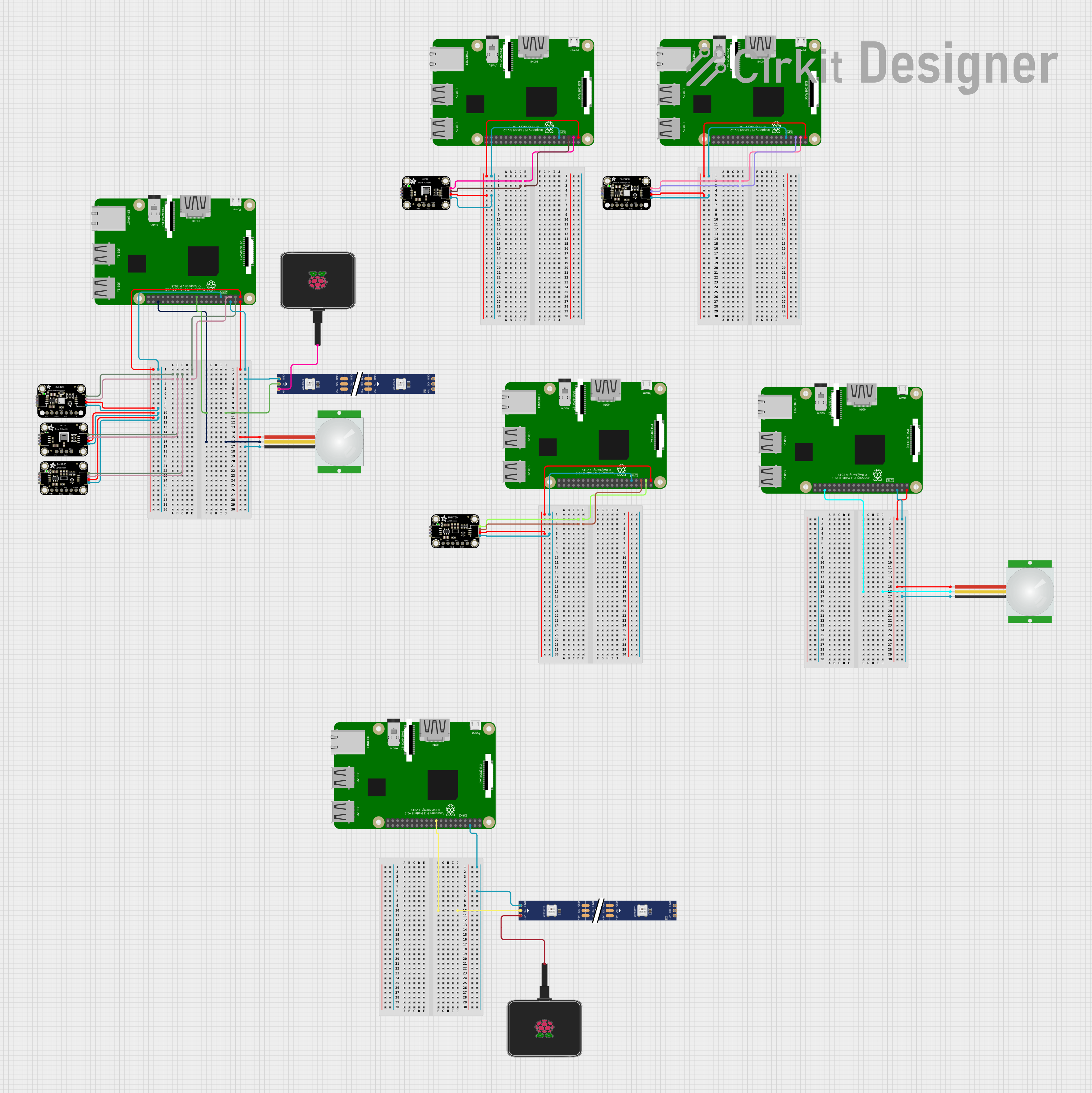
The circuit in question is designed to interface a Raspberry Pi 3B with a variety of sensors and peripherals. The sensors include the Adafruit BME680, Adafruit AHT20 Temperature and Humidity Sensors, Adafruit BH1750 light sensor, and PIR motion sensors. Additionally, the circuit controls a WS2812 RGB LED strip. The Raspberry Pi 3B serves as the central processing unit, managing data communication over I2C with the sensors and GPIO for the PIR sensor and LED strip. Power is supplied to the Raspberry Pi and the LED strip through dedicated power supplies.
Component List
Adafruit BME680
- Environmental sensor measuring temperature, humidity, barometric pressure, and VOC gas.
- Pins: VCC, 3.3V, GND, SCK/SCL, SDO/ADR, SDI/SDA, CS
Adafruit AHT20 Temperature and Humidity Sensor
- Sensor for measuring temperature and humidity.
- Pins: SCL, VCC, SDA, GND
Adafruit BH1750
- Digital light sensor providing ambient light intensity measurements.
- Pins: VCC, 3.3V, GND, SCL, SDA, ADDR
PIR Sensor
- Motion sensor detecting changes in infrared radiation levels.
- Pins: VDD, SIG, GND
WS2812 RGB LED Strip
- Addressable LED strip for display and lighting effects.
- Pins: DIN, 5V, GND, DO
Raspberry Pi 3B
- Microcomputer providing the main control and processing for the circuit.
- Pins: Multiple GPIOs, 3V3, 5V, GND
Raspberry Pi Power Supply
- Provides power to the Raspberry Pi and the LED strip.
Wiring Details
Adafruit BME680
- VCC connected to 3.3V from Raspberry Pi
- GND connected to GND on Raspberry Pi
- SCK/SCL connected to GPIO2 (SCL) on Raspberry Pi
- SDI/SDA connected to GPIO3 (SDA) on Raspberry Pi
Adafruit AHT20 Temperature and Humidity Sensor
- VCC connected to 3.3V from Raspberry Pi
- GND connected to GND on Raspberry Pi
- SCL connected to GPIO2 (SCL) on Raspberry Pi
- SDA connected to GPIO3 (SDA) on Raspberry Pi
Adafruit BH1750
- VCC connected to 3.3V from Raspberry Pi
- GND connected to GND on Raspberry Pi
- SCL connected to GPIO2 (SCL) on Raspberry Pi
- SDA connected to GPIO3 (SDA) on Raspberry Pi
PIR Sensor
- VDD connected to 5V from Raspberry Pi
- GND connected to GND on Raspberry Pi
- SIG connected to GPIO16 on Raspberry Pi
WS2812 RGB LED Strip
- DIN connected to GPIO10 on Raspberry Pi
- 5V connected to Raspberry Pi Power Supply
- GND connected to GND on Raspberry Pi
Code Documentation
No code has been provided for the microcontrollers in the circuit. The Raspberry Pi 3B would typically be programmed using Python or another suitable language to interface with the I2C sensors and control the GPIO pins for the PIR sensor and LED strip. The code would initialize the I2C bus, read sensor data, and respond to motion detection events, as well as control the LED strip based on the sensor inputs or other logic.