Cirkit Designer
Your all-in-one circuit design IDE
Home /
Project Documentation
Analog Multiplexer-Based Multi-Potentiometer Control System
Circuit Documentation
Summary
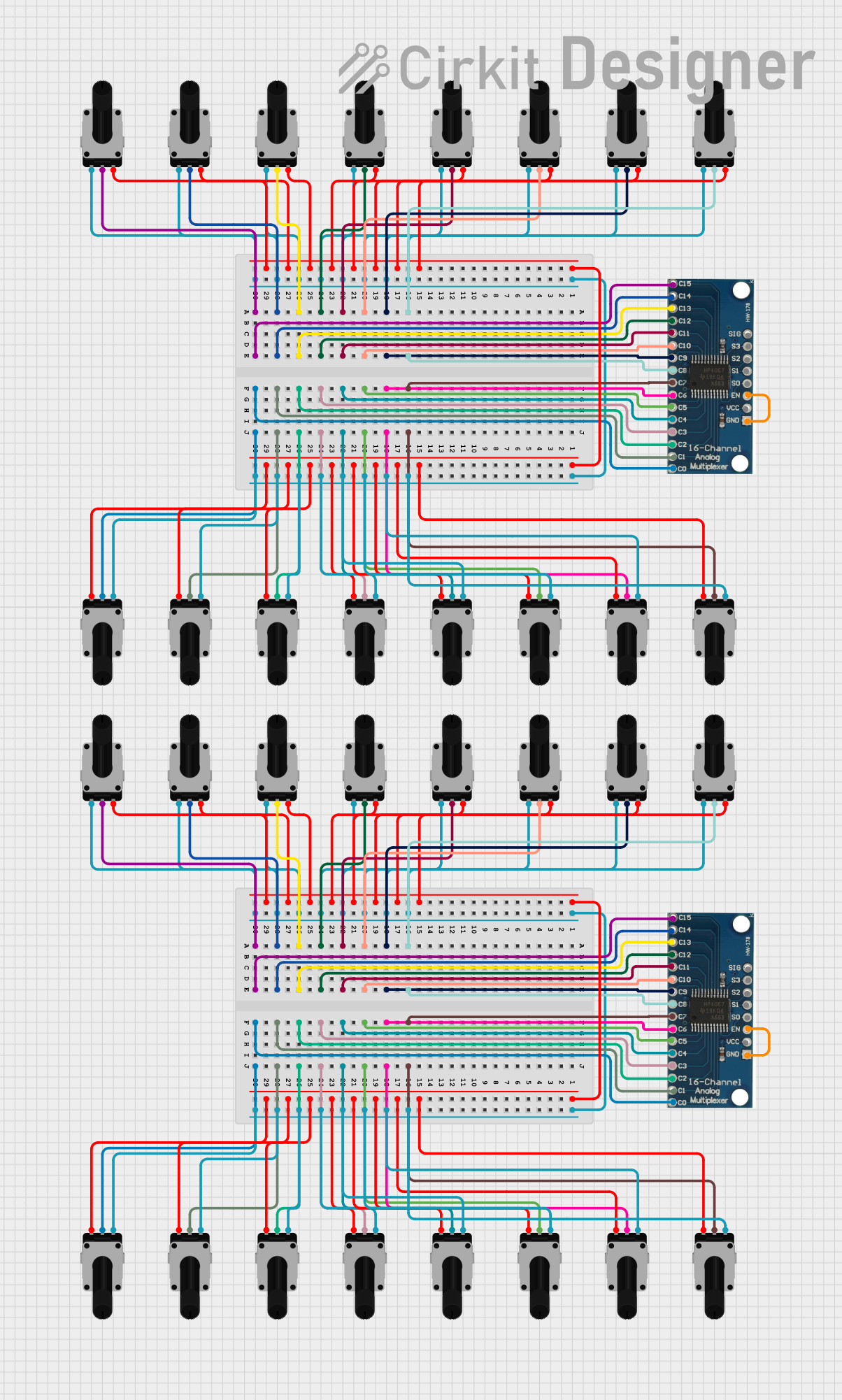
This circuit consists of multiple rotary potentiometers connected to two 16-channel analog multiplexers. The potentiometers are used to provide variable resistance, which is then read by the multiplexers. The multiplexers are configured to select one of the potentiometer signals at a time and output it to a common signal line. This setup allows for the reading of multiple potentiometer values using a single analog input on a microcontroller or other analog-to-digital conversion system.
Component List
16 Channel Analog Multiplexer
- Component Name: 16 channel analog multiplexer bob
- Description: A multiplexer that can select one of 16 input channels and output it to a single signal line.
- Pins: GND, VCC, EN, S0, S1, S2, S3, SIG, C0, C1, C2, C3, C4, C5, C6, C7, C8, C9, C10, C11, C12, C13, C14, C15
Rotary Potentiometer
- Component Name: Rotary Potentiometer
- Description: A variable resistor with three pins: two fixed ends and a wiper that moves along the resistive track.
- Pins: leg1, wiper, leg2
- Properties:
- Resistance: 10,000 Ohms
Wiring Details
16 Channel Analog Multiplexer (Instance 1)
- Pin Connections:
- GND: Connected to EN
- C0: Connected to wiper of Rotary Potentiometer (Instance 1)
- C1: Connected to wiper of Rotary Potentiometer (Instance 2)
- C2: Connected to wiper of Rotary Potentiometer (Instance 3)
- C3: Connected to wiper of Rotary Potentiometer (Instance 4)
- C4: Connected to wiper of Rotary Potentiometer (Instance 5)
- C5: Connected to wiper of Rotary Potentiometer (Instance 6)
- C6: Connected to wiper of Rotary Potentiometer (Instance 7)
- C7: Connected to wiper of Rotary Potentiometer (Instance 8)
- C8: Connected to wiper of Rotary Potentiometer (Instance 9)
- C9: Connected to wiper of Rotary Potentiometer (Instance 10)
- C10: Connected to wiper of Rotary Potentiometer (Instance 11)
- C11: Connected to wiper of Rotary Potentiometer (Instance 12)
- C12: Connected to wiper of Rotary Potentiometer (Instance 13)
- C13: Connected to wiper of Rotary Potentiometer (Instance 14)
- C14: Connected to wiper of Rotary Potentiometer (Instance 15)
- C15: Connected to wiper of Rotary Potentiometer (Instance 16)
16 Channel Analog Multiplexer (Instance 2)
- Pin Connections:
- GND: Connected to EN
- C0: Connected to wiper of Rotary Potentiometer (Instance 17)
- C1: Connected to wiper of Rotary Potentiometer (Instance 18)
- C2: Connected to wiper of Rotary Potentiometer (Instance 19)
- C3: Connected to wiper of Rotary Potentiometer (Instance 20)
- C4: Connected to wiper of Rotary Potentiometer (Instance 21)
- C5: Connected to wiper of Rotary Potentiometer (Instance 22)
- C6: Connected to wiper of Rotary Potentiometer (Instance 23)
- C7: Connected to wiper of Rotary Potentiometer (Instance 24)
- C8: Connected to wiper of Rotary Potentiometer (Instance 25)
- C9: Connected to wiper of Rotary Potentiometer (Instance 26)
- C10: Connected to wiper of Rotary Potentiometer (Instance 27)
- C11: Connected to wiper of Rotary Potentiometer (Instance 28)
- C12: Connected to wiper of Rotary Potentiometer (Instance 29)
- C13: Connected to wiper of Rotary Potentiometer (Instance 30)
- C14: Connected to wiper of Rotary Potentiometer (Instance 31)
- C15: Connected to wiper of Rotary Potentiometer (Instance 32)
Rotary Potentiometers
Common Connections:
- leg1: All leg1 pins of the rotary potentiometers are interconnected.
- leg2: All leg2 pins of the rotary potentiometers are interconnected.
Individual Connections:
- Instance 1: wiper connected to C0 of 16 Channel Analog Multiplexer (Instance 1)
- Instance 2: wiper connected to C1 of 16 Channel Analog Multiplexer (Instance 1)
- Instance 3: wiper connected to C2 of 16 Channel Analog Multiplexer (Instance 1)
- Instance 4: wiper connected to C3 of 16 Channel Analog Multiplexer (Instance 1)
- Instance 5: wiper connected to C4 of 16 Channel Analog Multiplexer (Instance 1)
- Instance 6: wiper connected to C5 of 16 Channel Analog Multiplexer (Instance 1)
- Instance 7: wiper connected to C6 of 16 Channel Analog Multiplexer (Instance 1)
- Instance 8: wiper connected to C7 of 16 Channel Analog Multiplexer (Instance 1)
- Instance 9: wiper connected to C8 of 16 Channel Analog Multiplexer (Instance 1)
- Instance 10: wiper connected to C9 of 16 Channel Analog Multiplexer (Instance 1)
- Instance 11: wiper connected to C10 of 16 Channel Analog Multiplexer (Instance 1)
- Instance 12: wiper connected to C11 of 16 Channel Analog Multiplexer (Instance 1)
- Instance 13: wiper connected to C12 of 16 Channel Analog Multiplexer (Instance 1)
- Instance 14: wiper connected to C13 of 16 Channel Analog Multiplexer (Instance 1)
- Instance 15: wiper connected to C14 of 16 Channel Analog Multiplexer (Instance 1)
- Instance 16: wiper connected to C15 of 16 Channel Analog Multiplexer (Instance 1)
- Instance 17: wiper connected to C0 of 16 Channel Analog Multiplexer (Instance 2)
- Instance 18: wiper connected to C1 of 16 Channel Analog Multiplexer (Instance 2)
- Instance 19: wiper connected to C2 of 16 Channel Analog Multiplexer (Instance 2)
- Instance 20: wiper connected to C3 of 16 Channel Analog Multiplexer (Instance 2)
- Instance 21: wiper connected to C4 of 16 Channel Analog Multiplexer (Instance 2)
- Instance 22: wiper connected to C5 of 16 Channel Analog Multiplexer (Instance 2)
- Instance 23: wiper connected to C6 of 16 Channel Analog Multiplexer (Instance 2)
- Instance 24: wiper connected to C7 of 16 Channel Analog Multiplexer (Instance 2)
- Instance 25: wiper connected to C8 of 16 Channel Analog Multiplexer (Instance 2)
- Instance 26: wiper connected to C9 of 16 Channel Analog Multiplexer (Instance 2)
- Instance 27: wiper connected to C10 of 16 Channel Analog Multiplexer (Instance 2)
- Instance 28: wiper connected to C11 of 16 Channel Analog Multiplexer (Instance 2)
- Instance 29: wiper connected to C12 of 16 Channel Analog Multiplexer (Instance 2)
- Instance 30: wiper connected to C13 of 16 Channel Analog Multiplexer (Instance 2)
- Instance 31: wiper connected to C14 of 16 Channel Analog Multiplexer (Instance 2)
- Instance 32: wiper connected to C15 of 16 Channel Analog Multiplexer (Instance 2)
Code
No code is provided for this circuit.