Arduino UNO Controlled Dual DC Motor Driver with ADXL335 Accelerometer Feedback
Circuit Documentation
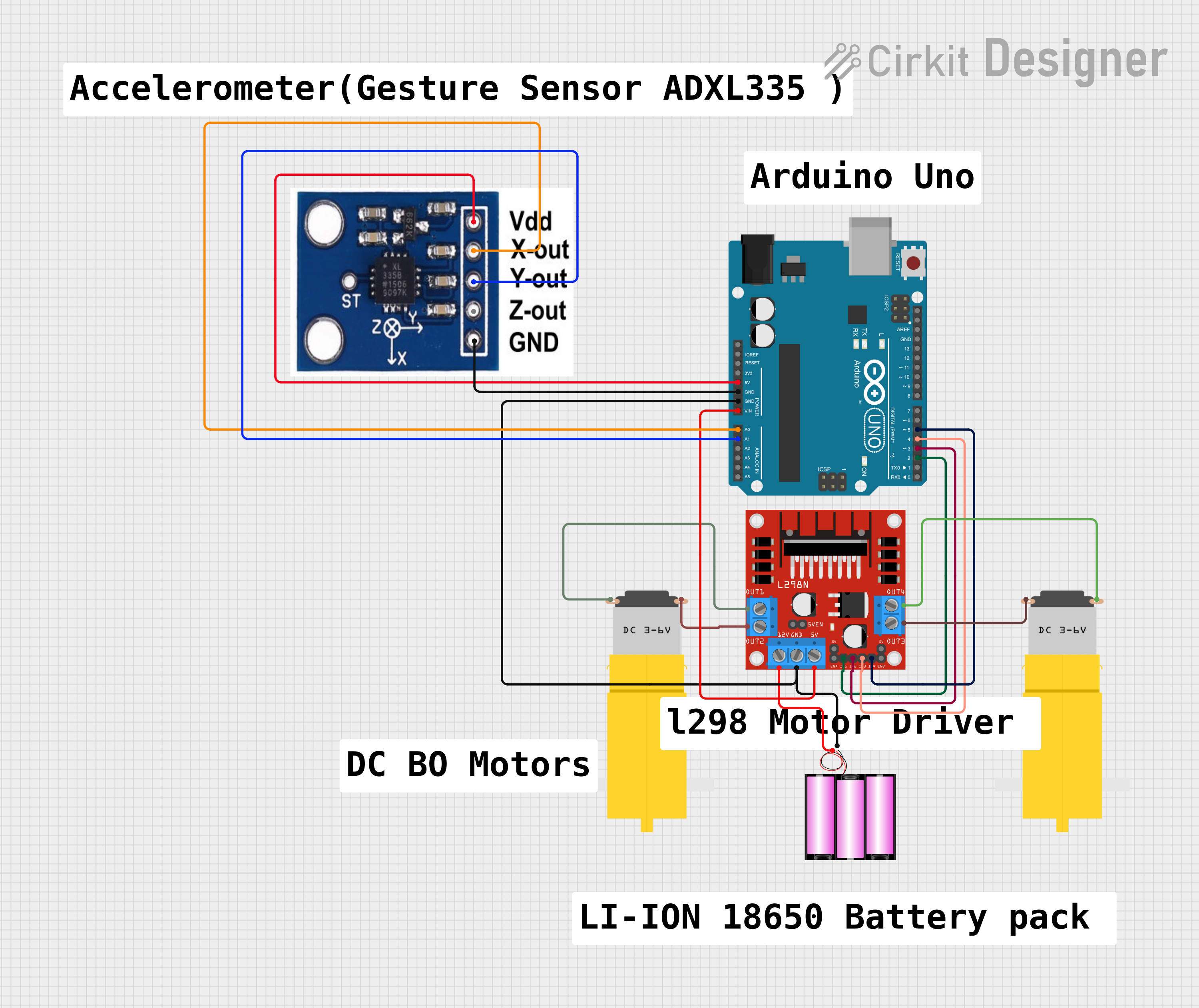
Summary
This circuit integrates an Arduino UNO microcontroller with an L298N DC motor driver to control two hobby motors. Additionally, an ADXXL335 accelerometer is connected to the Arduino to provide motion feedback. The system is powered by a 12V battery, which supplies power to the motor driver and, through a voltage regulator, to the Arduino. The Arduino controls the motor driver using digital output pins, and it reads the accelerometer data through analog input pins.
Component List
Arduino UNO
- Microcontroller board based on the ATmega328P
- Provides digital and analog I/O pins
- Can be powered via USB or external power supply
L298N DC Motor Driver
- Dual H-bridge motor driver
- Capable of driving two DC motors or one stepper motor
- Supports up to 2A per channel
Motor Amarillo Motorreductor Hobby (x2)
- Yellow DC gear motors commonly used in hobby projects
- Operates at nominal voltages around 6V to 12V
Battery 12V
- Provides the power source for the motor driver and indirectly for the Arduino through voltage regulation
ADXXL335 Accelerometer
- Measures acceleration in three axes: X, Y, and Z
- Provides analog voltage output proportional to acceleration
Wiring Details
Arduino UNO
5Vconnected to ADXXL335VCCGNDconnected to ADXXL335GNDand L298NGNDVinconnected to L298N5VA0connected to ADXXL335X-OUTA1connected to ADXXL335Y-OUTD2connected to L298NIN1D3connected to L298NIN2D4connected to L298NIN3D5connected to L298NIN4
L298N DC Motor Driver
GNDconnected to Battery(-)and Arduino UNOGND5Vconnected to Arduino UNOVin12Vconnected to Battery(+)IN1toIN4controlled by Arduino UNO digital pinsD2toD5OUT1andOUT2connected to one Motor AmarilloGNDandvccrespectivelyOUT3andOUT4connected to the other Motor AmarilloGNDandvccrespectively
Motor Amarillo Motorreductor Hobby
- One motor's
vccconnected to L298NOUT2,GNDtoOUT1 - The other motor's
vccconnected to L298NOUT4,GNDtoOUT3
Battery 12V
(+)connected to L298N12V(-)connected to L298NGND
ADXXL335 Accelerometer
VCCconnected to Arduino UNO5VGNDconnected to Arduino UNOGNDX-OUTconnected to Arduino UNOA0Y-OUTconnected to Arduino UNOA1
Documented Code
Arduino UNO Code (sketch.ino)
void setup() {
  // put your setup code here, to run once:

}

void loop() {
  // put your main code here, to run repeatedly:

}
Note: The provided code is a template and does not include specific functionality. It should be populated with the setup and loop routines required to initialize the pins and manage the motor driver and accelerometer.
Additional Files
- documentation.txt (Empty file, no code provided)
The code documentation is minimal as the provided code is only a template. Further implementation details should be added as the code is developed.