
Arduino UNO-Based Smart Sensor System with LCD Display and Servo Control
View and Edit Project In Cirkit Designer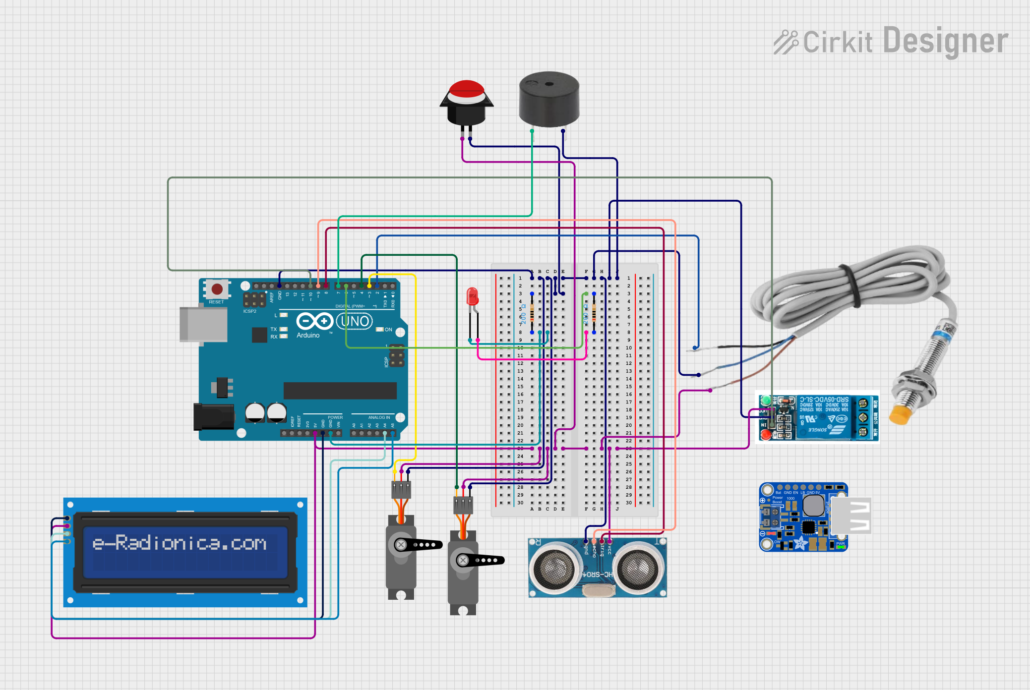
Circuit Documentation
Summary
This document provides a detailed overview of a circuit that includes an Arduino UNO microcontroller, various sensors, actuators, and other components. The circuit is designed to interface with multiple peripherals, including an ultrasonic sensor, inductive sensor, servos, an LCD screen, a push button, a relay, a buzzer, and LEDs. The Arduino UNO serves as the central control unit, executing the embedded code to manage the operations of the connected components.
Component List
Arduino UNO
- Description: Microcontroller board based on the ATmega328P.
- Pins: UNUSED, IOREF, Reset, 3.3V, 5V, GND, Vin, A0, A1, A2, A3, A4, A5, SCL, SDA, AREF, D13, D12, D11, D10, D9, D8, D7, D6, D5, D4, D3, D2, D1, D0
Inductive Sensor
- Description: Sensor used to detect metallic objects.
- Pins: black, blue, red
Servo (x2)
- Description: Actuator for precise control of angular position.
- Pins: GND, VCC, PWM
LCD Screen 16x2 I2C
- Description: 16x2 character LCD display with I2C interface.
- Pins: SCL, SDA, VCC, GND
Ultrasonic Sensor
- Description: Sensor for measuring distance using ultrasonic waves.
- Pins: +VCC, Trigger, Echo, GND
Push Button Round
- Description: Simple push button switch.
- Pins: leg0, leg1
5V Relay
- Description: Relay module for switching high voltage devices.
- Pins: Normally Open, Common terminal, Normally Closed, In, GND, VCC
PowerBoost 1000 Basic Terminal USB
- Description: Power supply module for boosting voltage to 5V.
- Pins: VBAT, GND, ENABLE, LBO, 5.0V
Buzzer
- Description: Audio signaling device.
- Pins: PIN, GND
Resistor (x2)
- Description: Passive electrical component with resistance.
- Pins: pin1, pin2
- Properties: Resistance: 200 Ohms
LED: Two Pin (red)
- Description: Light-emitting diode.
- Pins: cathode, anode
Wiring Details
Arduino UNO
- GND: Connected to GND of Ultrasonic Sensor, 5V Relay, Servo (x2), Inductive Sensor, Push Button Round, Buzzer, LCD Screen 16x2 I2C, and Resistor.
- 5V: Connected to VCC of Ultrasonic Sensor, 5V Relay, Servo (x2), Inductive Sensor, LCD Screen 16x2 I2C, and Push Button Round.
- A4: Connected to SDA of LCD Screen 16x2 I2C.
- A5: Connected to SCL of LCD Screen 16x2 I2C.
- D2: Connected to black pin of Inductive Sensor.
- D3: Connected to PWM pin of Servo.
- D4: Connected to PWM pin of Servo.
- D6: Connected to pin2 of Resistor.
- D7: Connected to PIN of Buzzer.
- D8: Connected to Trigger pin of Ultrasonic Sensor.
- D9: Connected to Echo pin of Ultrasonic Sensor.
- D10: Connected to In pin of 5V Relay.
Inductive Sensor
- black: Connected to D2 of Arduino UNO.
- blue: Connected to GND.
- red: Connected to 5V.
Servo (1)
- GND: Connected to GND.
- VCC: Connected to 5V.
- PWM: Connected to D3 of Arduino UNO.
Servo (2)
- GND: Connected to GND.
- VCC: Connected to 5V.
- PWM: Connected to D4 of Arduino UNO.
LCD Screen 16x2 I2C
- SCL: Connected to A5 of Arduino UNO.
- SDA: Connected to A4 of Arduino UNO.
- VCC: Connected to 5V.
- GND: Connected to GND.
Ultrasonic Sensor
- +VCC: Connected to 5V.
- Trigger: Connected to D8 of Arduino UNO.
- Echo: Connected to D9 of Arduino UNO.
- GND: Connected to GND.
Push Button Round
- leg0: Connected to 5V.
- leg1: Connected to GND.
5V Relay
- In: Connected to D10 of Arduino UNO.
- GND: Connected to GND.
- VCC: Connected to 5V.
Buzzer
- PIN: Connected to D7 of Arduino UNO.
- GND: Connected to GND.
Resistor (1)
- pin1: Connected to cathode of LED.
- pin2: Connected to GND.
Resistor (2)
- pin1: Connected to anode of LED.
- pin2: Connected to D6 of Arduino UNO.
LED: Two Pin (red)
- cathode: Connected to pin1 of Resistor.
- anode: Connected to pin1 of Resistor.
Documented Code
Arduino UNO Code (sketch.ino)
void setup() {
  // put your setup code here, to run once:

}

void loop() {
  // put your main code here, to run repeatedly:

}
Additional Documentation (documentation.txt)
This document provides a comprehensive overview of the circuit, including a summary, component list, wiring details, and documented code. Each component is described, and its connections are detailed to ensure clarity and ease of understanding.