ESP32-Based Wi-Fi Controlled Water Pump with LCD Interface
Circuit Documentation
Summary
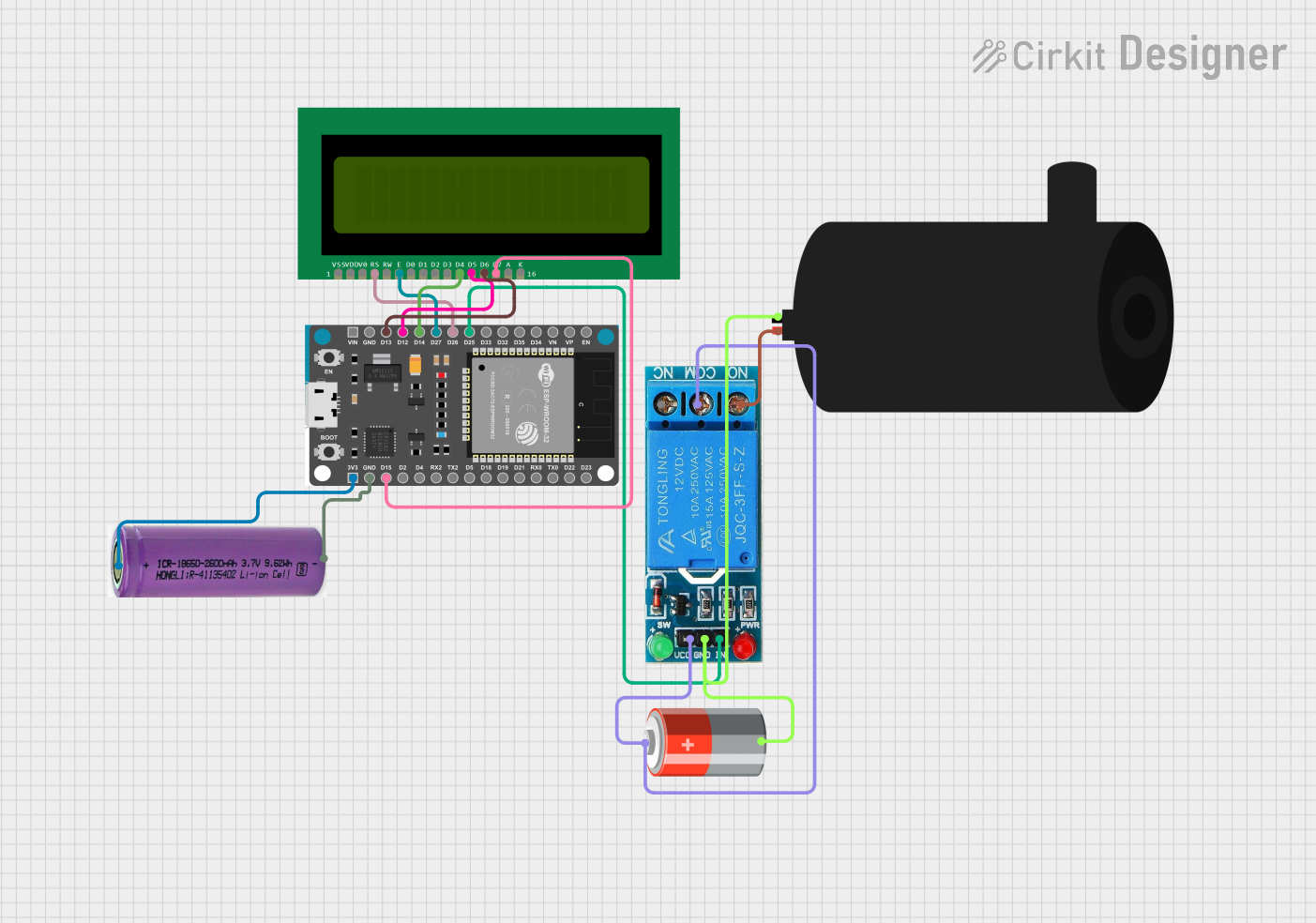
The circuit is designed to control a water pump using an ESP32 Devkit V1 microcontroller. The system can be operated remotely via a web server hosted on the ESP32, which allows the user to turn the water pump on and off. The status of the pump is displayed on a 16x2 LCD. The circuit includes a 12V single-channel relay to control the high-power circuit of the water pump, and it is powered by a 5V battery. Additionally, the ESP32 is powered by a separate 3.3V battery.
Component List
Water Pump
- Description: A device that moves water through mechanical action.
- Purpose: To pump water when activated by the relay.
16X2 LCD
- Description: A liquid crystal display capable of displaying 16 characters per line across 2 lines.
- Purpose: To display the status of the water pump.
12V Single Channel Relay
- Description: An electromechanical switch that allows a low-power circuit to control a high-power circuit.
- Purpose: To control the power to the water pump.
3.3V Battery
- Description: A power source providing 3.3 volts.
- Purpose: To power the ESP32 Devkit V1.
ESP32 Devkit V1
- Description: A microcontroller with Wi-Fi capabilities.
- Purpose: To control the relay and LCD, and to host the web server for remote operation.
5V Battery
- Description: A power source providing 5 volts.
- Purpose: To power the relay and potentially other 5V components in the circuit.
Wiring Details
Water Pump
- Positive: Connected to the Normally Open (NO) terminal of the 12V single-channel relay.
- Negative: Connected to the Ground (GND) terminal of the 12V single-channel relay and the negative terminal of the 5V battery.
16X2 LCD
- VSS: Not specified in the net list, typically connected to ground.
- VDD: Not specified in the net list, typically connected to a positive voltage supply.
- V0: Not specified in the net list, typically connected to a contrast adjustment potentiometer.
- RS: Connected to the D26 pin of the ESP32 Devkit V1.
- RW: Not specified in the net list, typically connected to ground if write-only mode is used.
- E: Connected to the D27 pin of the ESP32 Devkit V1.
- D4: Connected to the D14 pin of the ESP32 Devkit V1.
- D5: Connected to the D12 pin of the ESP32 Devkit V1.
- D6: Connected to the D13 pin of the ESP32 Devkit V1.
- D7: Connected to the D15 pin of the ESP32 Devkit V1.
- A: Not specified in the net list, typically connected to a positive voltage supply for backlight.
- K: Not specified in the net list, typically connected to ground for backlight.
12V Single Channel Relay
- NC: Not specified in the net list, typically left unconnected if not used.
- COM: Connected to the positive terminal of the 5V battery.
- NO: Connected to the positive terminal of the water pump.
- IN: Connected to the D25 pin of the ESP32 Devkit V1.
- GND: Connected to the negative terminal of the water pump and the negative terminal of the 5V battery.
- VCC: Connected to the positive terminal of the 5V battery.
3.3V Battery
- +: Connected to the 3V3 pin of the ESP32 Devkit V1.
- -: Connected to the GND pin of the ESP32 Devkit V1.
ESP32 Devkit V1
- 3V3: Connected to the positive terminal of the 3.3V battery.
- GND: Connected to the negative terminal of the 3.3V battery.
- D15, D2, D4, RX2, TX2, D5, D18, D19, D21, RX0, TX0, D22, D23, EN, VP, VN, D34, D35, D32, D33, D25, D26, D27, D14, D12, D13, VIN: Various connections to the 16X2 LCD and the 12V single-channel relay as detailed above.
5V Battery
- +: Connected to the VCC and COM terminals of the 12V single-channel relay.
- -: Connected to the GND terminal of the 12V single-channel relay.
Documented Code
#include <WiFi.h>
#include <WebServer.h>
#include <LiquidCrystal.h>

// Define constants
const char* ssid = "your_wifi_ssid";
const char* password = "your_wifi_password";

// Define pins
const int relayPin = 25;
const int lcdRS = 26;
const int lcdEN = 27;
const int lcdD4 = 14;
const int lcdD5 = 12;
const int lcdD6 = 13;
const int lcdD7 = 15;

// Initialize LCD
LiquidCrystal lcd(lcdRS, lcdEN, lcdD4, lcdD5, lcdD6, lcdD7);

// Create a web server on port 80
WebServer server(80);

bool pumpStatus = false;

void setup() {
  // Initialize serial communication
  Serial.begin(115200);

  // Connect to Wi-Fi
  WiFi.begin(ssid, password);
  while (WiFi.status() != WL_CONNECTED) {
    delay(1000);
    Serial.println("Connecting to WiFi...");
  }

  // Initialize relay pin as output
  pinMode(relayPin, OUTPUT);

  // Initialize LCD
  lcd.begin(16, 2);
  lcd.setCursor(0, 0);
  lcd.print("Water Pump Control");

  // Define web server routes
  server.on("/", []() {
    server.send(200, "text/html", "<a href=\"/on\">Turn On</a> <a href=\"/off\">Turn Off</a>");
  });

  server.on("/on", []() {
    pumpStatus = true;
    digitalWrite(relayPin, HIGH);
    lcd.setCursor(0, 1);
    lcd.print("Pump ON");
    server.send(200, "text/html", "Pump turned ON");
  });

  server.on("/off", []() {
    pumpStatus = false;
    digitalWrite(relayPin, LOW);
    lcd.setCursor(0, 1);
    lcd.print("Pump OFF");
    server.send(200, "text/html", "Pump turned OFF");
  });

  // Start the web server
  server.begin();
}

void loop() {
  // Handle web server requests
  server.handleClient();

  // Keep the motor on if pumpStatus is true
  if (pumpStatus) {
    digitalWrite(relayPin, HIGH);
  } else {
    digitalWrite(relayPin, LOW);
  }
}
This code is designed to run on the ESP32 Devkit V1 microcontroller. It sets up a Wi-Fi connection and a web server that allows remote control of the water pump. The LCD displays the current status of the pump, and the relay is used to switch the pump on and off based on web server requests.