
Circuit Documentation
Summary
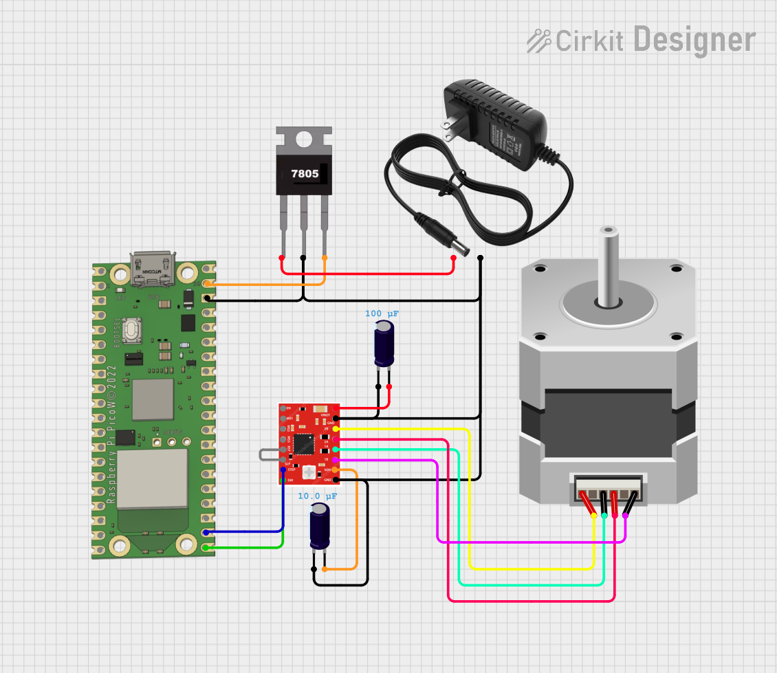
This circuit is designed to control a bipolar stepper motor using a Raspberry Pi Pico W microcontroller and an A988 stepper motor driver. The circuit is powered by a 12V power supply, which is regulated down to 5V by a 7805 voltage regulator to power the Raspberry Pi Pico W and the logic side of the A988 driver. The stepper motor is driven by the A988 driver, which receives its control signals from the Raspberry Pi Pico W. Capacitors are used for voltage smoothing on both the input and output sides of the voltage regulator.
Component List
Raspberry Pi Pico W
- Microcontroller board with a variety of GPIO pins.
- Utilized for controlling the A988 driver and managing the stepper motor's movements.
A988 Stepper Motor Driver
- A motor driver capable of driving a bipolar stepper motor.
- Receives direction and step signals from the Raspberry Pi Pico W.
7805 Voltage Regulator
- A linear voltage regulator that outputs a stable 5V from a higher voltage input (up to 35V).
- Used to provide a regulated 5V supply to the Raspberry Pi Pico W and the A988 driver logic.
12V Power Supply
- Provides the main power source for the circuit.
- Supplies power to the 7805 voltage regulator and the A988 driver for the motor.
Electrolytic Capacitors
- Two capacitors with different capacitance values.
- Used for smoothing voltage fluctuations on the power supply lines.
Stepper Motor (Bipolar)
- A bipolar stepper motor controlled by the A988 driver.
- Converts electrical pulses into mechanical rotation.
Wiring Details
Raspberry Pi Pico W
VSYSconnected toVoutof the 7805 voltage regulator.GP16connected toDIRpin of the A988 driver to control the direction.GP17connected toSTEPpin of the A988 driver to control the stepping.GNDconnected to the common ground net.
A988 Stepper Motor Driver
VMOTconnected to the positive side of the 12V power supply through a capacitor.GNDconnected to the common ground net.2B,2A,1A,1Bconnected to the corresponding pinsA,B,C,Dof the stepper motor.VDDconnected to the 5V output from the 7805 voltage regulator through a capacitor.DIRandSTEPconnected toGP16andGP17on the Raspberry Pi Pico W, respectively.RSTandSLPare shorted together, possibly for enabling the driver.
7805 Voltage Regulator
Vinconnected to the positive side of the 12V power supply.Gndconnected to the common ground net.Voutconnected toVSYSof the Raspberry Pi Pico W andVDDof the A988 driver through a capacitor.
12V Power Supply
+connected toVinof the 7805 voltage regulator andVMOTof the A988 driver through a capacitor.-connected to the common ground net.
Electrolytic Capacitors
- One capacitor connected between
VinandGndof the 7805 voltage regulator. - Another capacitor connected between
Voutof the 7805 andVDDof the A988 driver.
Stepper Motor (Bipolar)
A,B,C,Dconnected to2B,2A,1A,1Bof the A988 driver, respectively.
Documented Code
No code has been provided for the microcontroller. The documentation for the code would typically include a description of the functionality, setup, and main loop, along with comments explaining the purpose of each section of the code. Since no code is available, this section cannot be completed.