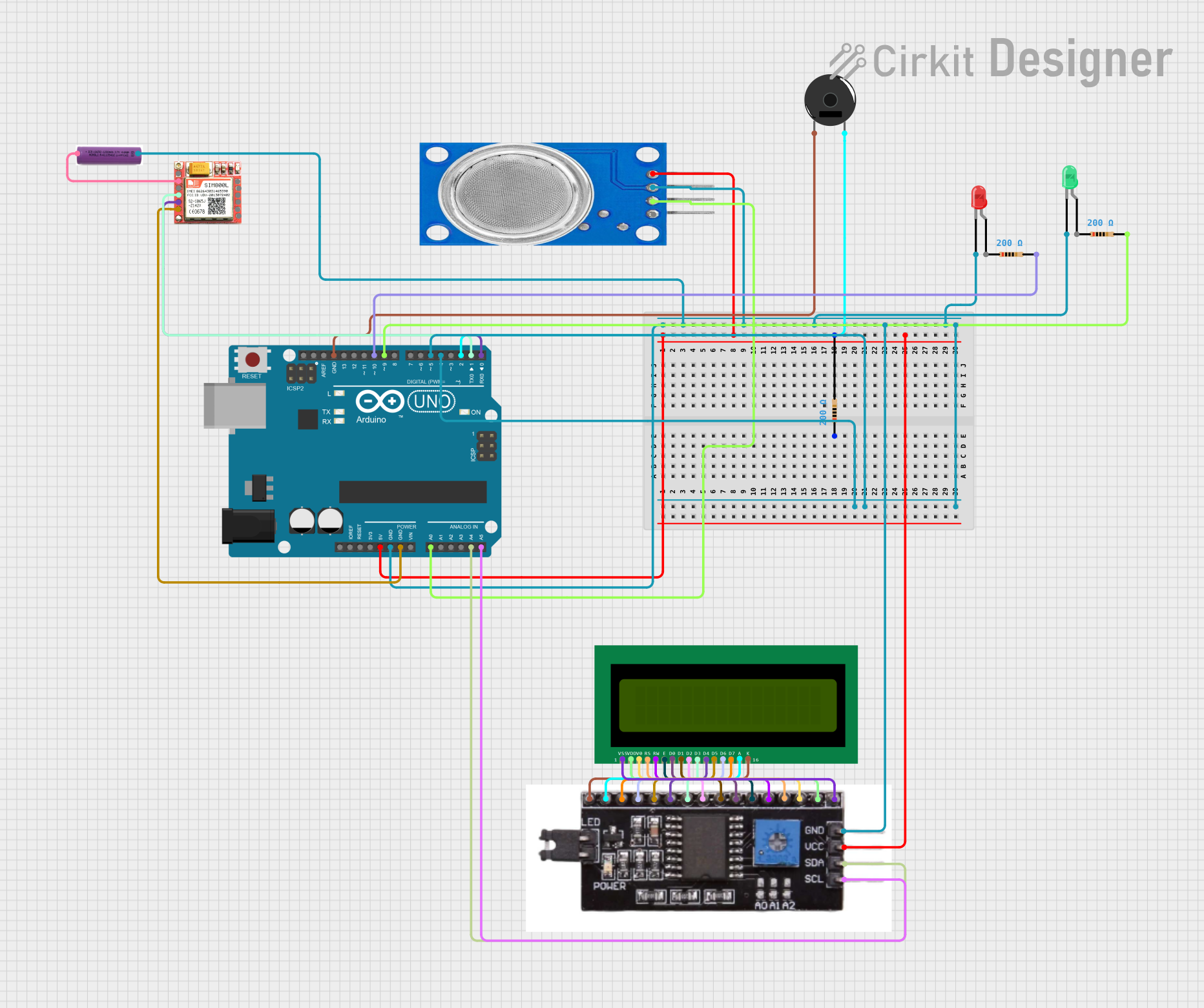
Arduino-Based Gas Detection and Alert System with GSM Notification

Circuit Documentation
Summary
The circuit in question is designed to monitor air quality using an MQ135 gas sensor and to alert users of gas leaks via visual indicators (LEDs), an audible alarm (Piezo Buzzer), and GSM communication (SIM800L module). The Arduino UNO serves as the central microcontroller, interfacing with the MQ135 sensor, LEDs, buzzer, and SIM800L module. An I2C module is used to facilitate communication between the Arduino and a 16x2 LCD display for real-time air quality readings. The circuit is powered by a 3.7V battery.
Component List
Resistor
- Description: A passive two-terminal electrical component that implements electrical resistance as a circuit element.
- Properties: 200 Ohms resistance.
Piezo Buzzer
- Description: An electronic device that emits sound when an electric current is passed through it.
- Purpose: To provide an audible alert in case of gas detection.
LED: Two Pin (red)
- Description: A red light-emitting diode that emits red light when a current flows through it.
- Purpose: To visually indicate an alert condition.
LED: Two Pin (green)
- Description: A green light-emitting diode that emits green light when a current flows through it.
- Purpose: To visually indicate a normal condition.
SIM800L
- Description: A GSM/GPRS module that allows the circuit to communicate over cellular networks.
- Purpose: To send SMS alerts and make calls in case of gas detection.
3.7V Battery
- Description: A power source for the circuit.
- Purpose: To provide electrical power to the circuit.
MQ135
- Description: An air quality sensor capable of detecting a wide range of gases, including NH3, NOx, alcohol, benzene, smoke, and CO2.
- Purpose: To monitor the air quality for hazardous gases.
16X2 LCD
- Description: A liquid crystal display capable of displaying 16 characters per line across 2 lines.
- Purpose: To display the air quality index and gas detection status.
I2C Module
- Description: A communication module that allows for serial computer bus for the inter-communication of integrated circuits.
- Purpose: To interface the 16x2 LCD with the Arduino UNO using the I2C protocol.
Arduino UNO
- Description: A microcontroller board based on the ATmega328P.
- Purpose: To control the operation of the circuit, read sensor data, drive the LEDs, buzzer, and manage GSM communication.
Wiring Details
Resistor
- Connected to the Arduino UNO's 5V output to limit current.
Piezo Buzzer
- One pin connected to the Arduino UNO's digital pin for control.
- The other pin connected to the ground.
LED: Two Pin (red)
- Anode connected to a digital pin on the Arduino UNO through a resistor.
- Cathode connected to the ground.
LED: Two Pin (green)
- Anode connected to a digital pin on the Arduino UNO through a resistor.
- Cathode connected to the ground.
SIM800L
- VCC connected to the 3.7V battery's positive terminal.
- GND connected to the ground.
- RXD connected to the Arduino UNO's TX pin.
- TXD connected to the Arduino UNO's RX pin.
3.7V Battery
- Positive terminal providing power to the circuit.
- Negative terminal connected to the ground.
MQ135
- VCC connected to the Arduino UNO's 5V output.
- GND connected to the ground.
- A0 connected to the Arduino UNO's analog input.
16X2 LCD
- Interfaced with the Arduino UNO via the I2C Module.
I2C Module
- VCC connected to the Arduino UNO's 5V output.
- GND connected to the ground.
- SDA connected to the Arduino UNO's A4 pin.
- SCL connected to the Arduino UNO's A5 pin.
Documented Code
#include <Wire.h>
#include <LiquidCrystal_I2C.h>
#include <SoftwareSerial.h>

#define MQ135_PIN A0
#define RED_LED_PIN 4
#define GREEN_LED_PIN 5
#define BUZZER_PIN 2
#define GSM_RX_PIN 1
#define GSM_TX_PIN 0

LiquidCrystal_I2C lcd(0x27, 16, 2);
SoftwareSerial gsm(GSM_RX_PIN, GSM_TX_PIN);

const int threshold = 310;
const unsigned long smsInterval = 60000;
const unsigned long callInterval = 180000;
unsigned long lastSmsTime = 0;
unsigned long lastCallTime = 0;

// Timer variables for LED blinking and buzzer activation
unsigned long ledBlinkTimer = 0;
unsigned long buzzerTimer = 0;

void setup() {
  pinMode(RED_LED_PIN, OUTPUT);
  pinMode(GREEN_LED_PIN, OUTPUT);
  pinMode(BUZZER_PIN, OUTPUT);
  lcd.begin();
  lcd.backlight();
  gsm.begin(9600);
  digitalWrite(GREEN_LED_PIN, HIGH);
}

void loop() {
  int mq135Value = analogRead(MQ135_PIN);
  lcd.setCursor(0, 0);
  if (mq135Value > threshold) {
    lcd.print("Gas Detected");
    digitalWrite(GREEN_LED_PIN, LOW);
    startBlinkingRedLed();
    startBuzzer();
    sendAlert();
  } else {
    lcd.print("No Gas Detected");
    digitalWrite(GREEN_LED_PIN, HIGH);
    digitalWrite(RED_LED_PIN, LOW);
    noTone(BUZZER_PIN);
  }
  lcd.setCursor(0, 1);
  lcd.print("AQI: ");
  lcd.print(mq135Value);
  handleLedBlinking();
  handleBuzzer();
  delay(1000);
}

void startBlinkingRedLed() {
  ledBlinkTimer = millis();
}

void handleLedBlinking() {
  if (millis() - ledBlinkTimer >= 500) {
    digitalWrite(RED_LED_PIN, !digitalRead(RED_LED_PIN));
    ledBlinkTimer = millis();
  }
}

void startBuzzer() {
  buzzerTimer = millis();
  tone(BUZZER_PIN, 325);
}

void handleBuzzer() {
  if (millis() - buzzerTimer >= 5000) {
    noTone(BUZZER_PIN);
  }
}

void sendAlert() {
  sendSms();
  makeCall();
}

void sendSms() {
  unsigned long currentTime = millis();
  if (currentTime - lastSmsTime >= smsInterval) {
    gsm.print("AT+CMGF=1\r");
    delay(100);
    gsm.print("AT+CMGS=\"+918446656933\"\r");
    delay(100);
    gsm.print("Gas leakage detected");
    delay(100);
    gsm.write(26);
    lastSmsTime = currentTime;
  }
}

void makeCall() {
  unsigned long currentTime = millis();
  if (currentTime - lastCallTime >= callInterval) {
    gsm.print("ATD+918446656933;\r");
    delay(30000);
    gsm.print("ATH\r");
    lastCallTime = currentTime;
  }
}
This code is responsible for reading the MQ135 sensor data, controlling the LEDs and buzzer based on the gas levels, and using the SIM800L module to send SMS alerts and make calls when gas is detected. The LCD displays the current air quality index and status messages.