
ESP32-Based Smart Irrigation and Environmental Monitoring System
View and Edit Project In Cirkit Designer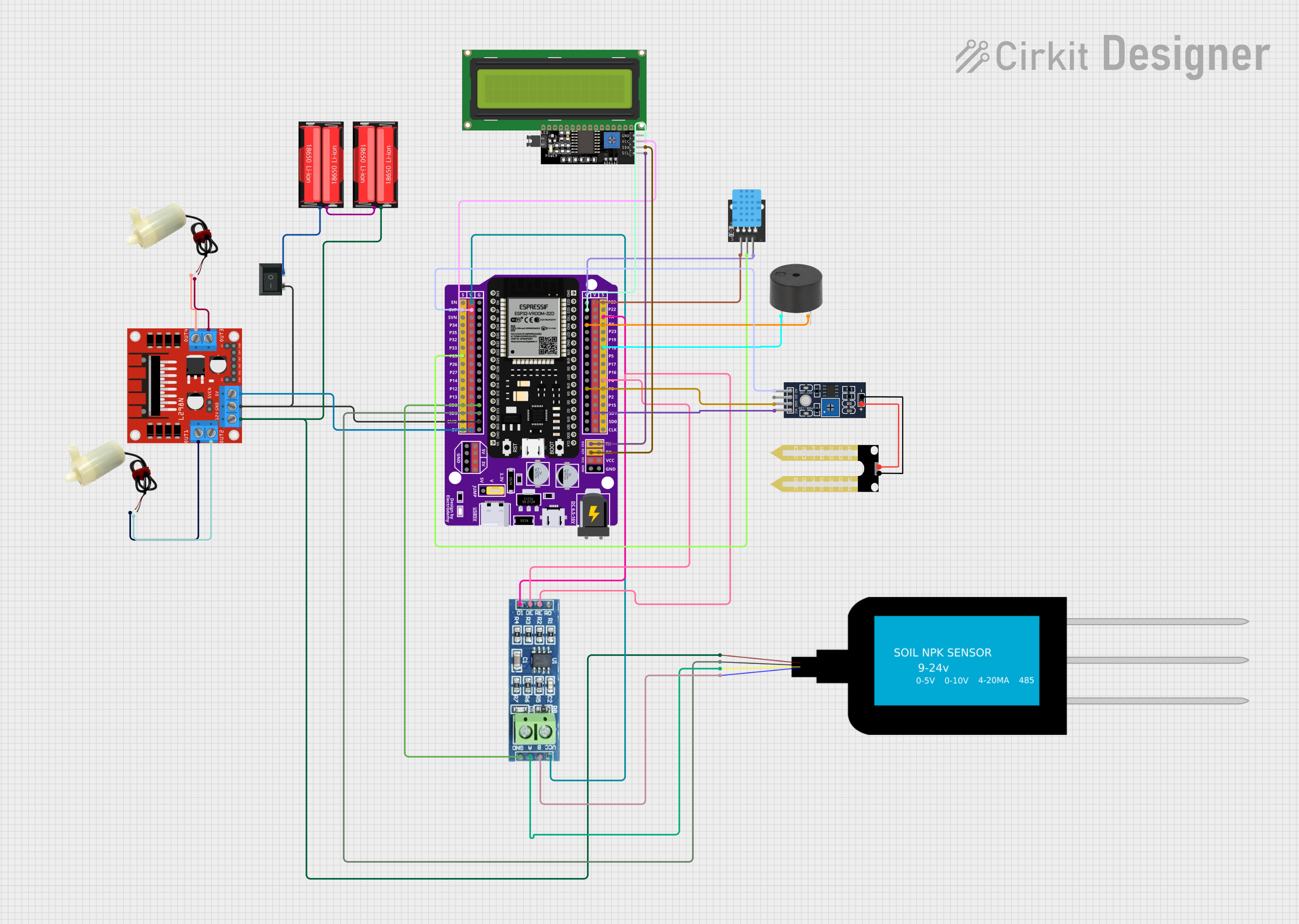
Circuit Documentation
Summary
This circuit integrates various components to perform multiple functions. It is centered around the ESP32 microcontroller, which is responsible for controlling a DC motor via the L298N motor driver, reading temperature and humidity data from a DHT11 sensor, interfacing with an RS485 module for serial communication, and displaying information on an LCD display with I2C interface. The circuit also includes a humidity sensor (YL-69), a buzzer for audio feedback, and a soil NPK sensor for measuring soil nutrients. Power management is handled by 18650 Li-Ion batteries and a rocker switch. The circuit is designed for applications that require environmental monitoring and actuation based on sensor inputs.
Component List
ESP32 - 38 pins Expansion Board
- Microcontroller with Wi-Fi and Bluetooth capabilities.
- 38 pins for various I/O functions.
L298N DC Motor Driver
- Module for driving DC motors.
- Contains pins for motor outputs and power inputs.
5V Mini Water Pump
- A small pump for moving water.
- Has positive and negative power pins.
KY-015 DHT11 Temperature and Humidity Sensor
- Sensor for measuring temperature and humidity.
- Includes pins for data, power, and ground.
18650 Li-Ion Battery
- Rechargeable lithium-ion battery.
- Provides power to the circuit.
Buzzer
- An audible signaling device.
- Has pins for signal input and ground.
Humidity YL-69 Sensor
- Soil moisture sensor.
- Features analog and digital outputs.
Rocker Switch (SPST)
- Single Pole Single Throw switch.
- Used for power control.
NPK Soil Sensor
- Sensor for measuring soil nutrient content.
- Has pins for power, ground, and analog outputs.
RS485 Module
- Serial communication module based on RS485 standard.
- Includes pins for data transmission and reception.
LCD Display 16x4 I2C
- Liquid crystal display with I2C interface.
- Used for displaying information.
Wiring Details
ESP32 - 38 pins Expansion Board
SVPconnected to Humidity YL-69A0P25connected to KY-015 DHT11STXconnected to RS485DIP18connected to BuzzerPINP4connected to RS485REandDED22connected to LCD Display 16x4 I2CSCLD21connected to LCD Display 16x4 I2CSDAVconnected to RS485VCC, LCD Display 16x4 I2CVCC, L298N DC Motor Driver5V, KY-015 DHT115V, Humidity YL-69VCCGconnected to RS485GND, NPK Soil SensorGND, L298N DC Motor DriverGND(via Rocker Switch2), KY-015 DHT11GND, LCD Display 16x4 I2CGND, BuzzerGND, Humidity YL-69GND
L298N DC Motor Driver
OUT1connected to 5V Mini Water Pumppositive pinOUT2connected to 5V Mini Water Pumpnegative pinOUT3connected to 5V Mini Water Pumpnegative pinOUT4connected to 5V Mini Water Pumppositive pin12Vconnected to NPK Soil SensorVCCand 18650 Li-Ion BatteryPositive
5V Mini Water Pump
- One pump's
positive pinconnected to L298N DC Motor DriverOUT1 - The same pump's
negative pinconnected to L298N DC Motor DriverOUT2 - Another pump's
negative pinconnected to L298N DC Motor DriverOUT3 - The same pump's
positive pinconnected to L298N DC Motor DriverOUT4
KY-015 DHT11 Temperature and Humidity Sensor
Sconnected to ESP32P255VandGNDconnected to ESP32VandG
18650 Li-Ion Battery
- One battery's
Positiveconnected to another battery'sNegative Positiveconnected to L298N DC Motor Driver12VNegativeconnected to Rocker Switch1
Buzzer
PINconnected to ESP32P18GNDconnected to ESP32G
Humidity YL-69 Sensor
A0connected to ESP32SVPVCCandGNDconnected to ESP32VandG
Rocker Switch (SPST)
1connected to 18650 Li-Ion BatteryNegative2connected to L298N DC Motor DriverGND
NPK Soil Sensor
GNDconnected to ESP32GVCCconnected to L298N DC Motor Driver12VAconnected to RS485ABconnected to RS485B
RS485 Module
VCCandGNDconnected to ESP32VandGDIconnected to ESP32TXREandDEconnected to ESP32P4Aconnected to NPK Soil SensorABconnected to NPK Soil SensorB
LCD Display 16x4 I2C
SCLconnected to ESP32D22SDAconnected to ESP32D21VCCandGNDconnected to ESP32VandG
Documented Code
No code was provided for the microcontrollers in the circuit. The documentation of the code would typically include descriptions of the functions, initialization procedures, main loop, and any interrupt service routines. It would also detail how the code interacts with the connected sensors and actuators, as well as any communication protocols used. Since no code is available, this section cannot be completed.