Cirkit Designer
Your all-in-one circuit design IDE
Home /
Project Documentation
Air Quality and Humidity Monitoring System with NodeMCU and I2C LCD Display
Circuit Documentation
Summary
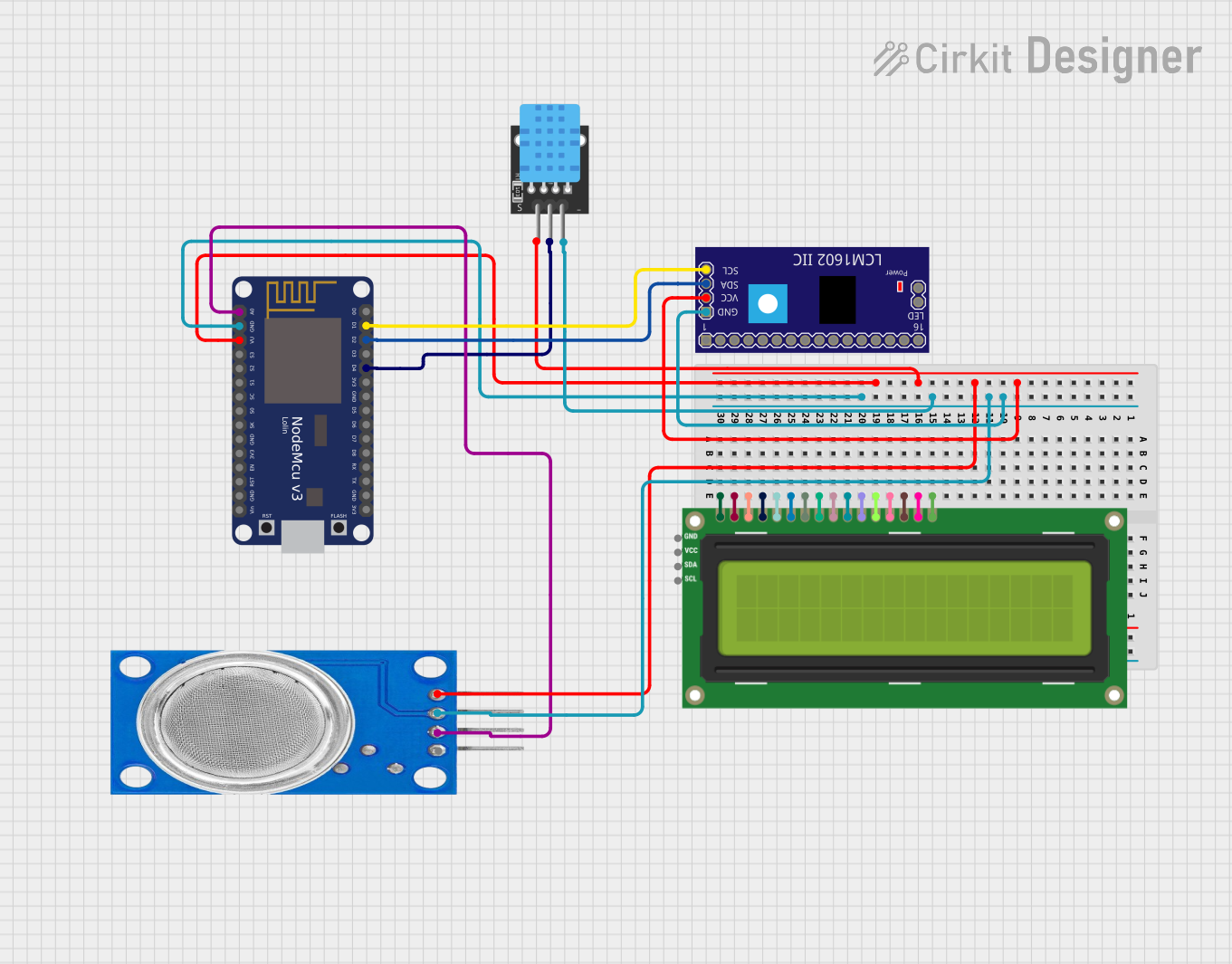
The circuit is designed to monitor air quality and humidity levels, displaying the data on an I2C LCD 16x2 screen. It consists of an MQ135 gas sensor for air quality detection, a DHT11 sensor for measuring temperature and humidity, and a NodeMCU V3 ESP8266 microcontroller for processing sensor data and controlling the LCD display. The circuit is powered through a common VCC line and grounded through a common GND line.
Component List
MQ135 Gas Sensor
- Pins: VCC, GND, A0, D0
- Description: This sensor is used for air quality monitoring, capable of detecting a wide range of gases, including NH3, NOx, alcohol, benzene, smoke, and CO2.
DHT11 Temperature and Humidity Sensor
- Pins: 5V, S, GND
- Description: The DHT11 sensor measures ambient temperature and humidity.
LCM1602 IIC Module
- Pins: GND, VCC, SDA, SCL, and others not used in this circuit.
- Description: This module is an I2C interface for LCDs, simplifying the number of pins required to control the LCD.
NodeMCU V3 ESP8266
- Pins: A0, GND, VU, S3, S2, S1, SC, S0, SK, 3V3, EN, RST, Vin, D0, D1, D2, D3, D4, D5, D6, D7, D8, RX, TX
- Description: The NodeMCU V3 is a microcontroller board based on the ESP8266 chip, featuring Wi-Fi capabilities and a wide range of GPIO pins.
I2C LCD 16x2 Screen
- Pins: SCL, SDA, VCC (5V), GND, VDD, VO, RS, RW, E, D0, D1, D2, D3, D4, D5, D6, D7, BLA, BLK
- Description: This is a 16x2 character LCD display that uses the I2C communication protocol for displaying text and characters.
Wiring Details
MQ135 Gas Sensor
- VCC: Connected to the common VCC line.
- GND: Connected to the common GND line.
- A0: Connected to the A0 pin on the NodeMCU V3 ESP8266.
DHT11 Temperature and Humidity Sensor
- 5V: Connected to the common VCC line.
- S: Connected to the D4 pin on the NodeMCU V3 ESP8266.
- GND: Connected to the common GND line.
LCM1602 IIC Module
- VCC: Connected to the common VCC line.
- GND: Connected to the common GND line.
- SDA: Connected to the D2 pin on the NodeMCU V3 ESP8266.
- SCL: Connected to the D1 pin on the NodeMCU V3 ESP8266.
NodeMCU V3 ESP8266
- VU: Connected to the common VCC line.
- GND: Connected to the common GND line.
- A0: Connected to the A0 pin on the MQ135 Gas Sensor.
- D4: Connected to the S pin on the DHT11 Sensor.
- D2: Connected to the SDA pin on the LCM1602 IIC Module.
- D1: Connected to the SCL pin on the LCM1602 IIC Module.
I2C LCD 16x2 Screen
- SCL: Connected to the SCL pin on the LCM1602 IIC Module.
- SDA: Connected to the SDA pin on the LCM1602 IIC Module.
- VCC (5V): Connected to the common VCC line.
- GND: Connected to the common GND line.
Documented Code
NodeMCU V3 ESP8266 Code
/*
 * Air Quality and Humidity Monitoring System
 * This Arduino sketch reads data from an MQ135 gas sensor and a DHT11
 * humidity sensor, and displays the temperature, humidity, and air quality
 * on an I2C LCD 16x2 screen. The system is designed to track air quality
 * and humidity for healthier air and informed decisions.
 */

#include <DHT.h>
#include <Wire.h>
#include <LiquidCrystal_I2C.h>

#define DHTPIN D4 // Pin connected to the DHT11 sensor
#define DHTTYPE DHT11 // DHT 11
#define MQ135PIN A0 // Pin connected to the MQ135 sensor

DHT dht(DHTPIN, DHTTYPE);
LiquidCrystal_I2C lcd(0x27, 16, 2);

void setup() {
  Serial.begin(9600); // Initialize serial communication at 9600 baud rate
  dht.begin(); // Initialize the DHT sensor
  lcd.init(); // Initialize the LCD
  lcd.backlight(); // Turn on the backlight of the LCD
}

void loop() {
  // Read data from sensors
  float temp = dht.readTemperature(); // Read temperature in Celsius
  float hum = dht.readHumidity(); // Read humidity percentage
  int airQuality = analogRead(MQ135PIN); // Read air quality from MQ135

  // Display data on LCD
  lcd.setCursor(0, 0);
  lcd.print("Temp: ");
  lcd.print(temp);
  lcd.print("C");
  lcd.setCursor(0, 1);
  lcd.print("Hum: ");
  lcd.print(hum);
  lcd.print("%");
  lcd.setCursor(8, 1);
  lcd.print("AQ: ");
  lcd.print(airQuality);
  lcd.print("ppm");

  // Print data to Serial Monitor
  Serial.print("Temperature: ");
  Serial.print(temp);
  Serial.print("C");
  Serial.print(" Humidity: ");
  Serial.print(hum);
  Serial.print("%");
  Serial.print(" Air Quality: ");
  Serial.print(airQuality);
  Serial.println("ppm");

  delay(2000); // Wait for 2 seconds before next read
}
DHT11 Sensor Code
/*
 * Real-time Air Quality Monitoring System
 * This Arduino sketch reads data from a DHT11 sensor and displays the
 * temperature and humidity on the Serial Monitor. The system is designed
 * to track air quality for healthier air and informed decisions.
 */

#include <DHT.h>

#define DHTPIN D4 // Pin connected to the DHT11 sensor
#define DHTTYPE DHT11 // DHT 11

DHT dht(DHTPIN, DHTTYPE);

void setup() {
  Serial.begin(9600); // Initialize serial communication at 9600 baud rate
  dht.begin(); // Initialize the DHT sensor
}

void loop() {
  // Read data from the DHT11 sensor
  float temp = dht.readTemperature(); // Read temperature in Celsius
  float hum = dht.readHumidity(); // Read humidity percentage
  if (isnan(temp) || isnan(hum)) {
    Serial.println("Failed to read from DHT sensor!");
  }
  else {
    // Print data to Serial Monitor
    Serial.print("Temperature: ");
    Serial.print(temp);
    Serial.print("C");
    Serial.print(" Humidity: ");
    Serial.print(hum);
    Serial.println("%");

    delay(2000); // Wait for 2 seconds before next read
  }
}
(Note: The code for the MQ135 sensor and the I2C LCD 16x2 Screen is integrated into the NodeMCU V3 ESP8266 code section above.)