
Arduino-Controlled NRF24L01 Wireless Potentiometer Data Transmission System
View and Edit Project In Cirkit Designer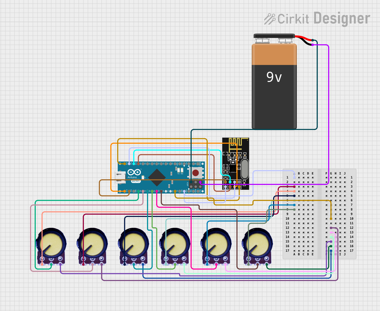
Circuit Documentation
Summary
This circuit is designed to read analog values from multiple potentiometers and transmit the readings wirelessly using an NRF24L01 transceiver module. An Arduino Micro (Rev3) serves as the central microcontroller, interfacing with the potentiometers and the NRF24L01 module. The Arduino is powered by a 9V battery and regulates the voltage to 5V for the potentiometers and 3.3V for the NRF24L01. The potentiometer readings are sent over SPI to the NRF24L01, which transmits the data to a remote receiver.
Component List
Arduino Micro (Rev3)
- Microcontroller board based on the ATmega32U4
- Features digital I/O pins, analog input pins, and PWM pins
- Includes hardware support for SPI communication
Potentiometer (x6)
- Three-terminal variable resistor
- Provides an adjustable voltage output
NRF24L01
- 2.4GHz wireless transceiver module
- Interfaces with the microcontroller via SPI
- Operates at 3.3V
9V Battery
- Provides power to the circuit
- Connected to the Arduino Micro for voltage regulation
Wiring Details
Arduino Micro (Rev3)
- 5V: Powers the potentiometers
- GND: Common ground for the circuit
- 3V3: Powers the NRF24L01 module
- D9 PWM/A9: Connected to the CE pin of the NRF24L01
- D10 PWM/A10: Connected to the CSN pin of the NRF24L01
- D11 PWM: Connected to the MOSI pin of the NRF24L01
- D12 PWM/A11: Connected to the MISO pin of the NRF24L01
- D13 PWM: Connected to the SCK pin of the NRF24L01
- A0 - A5: Connected to the output pins of the potentiometers
Potentiometer
- GND: Connected to the ground of the circuit
- Output: Connected to the analog input pins on the Arduino Micro (A0 - A5)
- VCC: Powered by the 5V output from the Arduino Micro
NRF24L01
- GND: Common ground with the Arduino Micro
- VCC (3V): Powered by the 3.3V output from the Arduino Micro
- CE: Connected to D9 on the Arduino Micro
- CSN: Connected to D10 on the Arduino Micro
- MOSI: Connected to D11 on the Arduino Micro
- MISO: Connected to D12 on the Arduino Micro
- SCK: Connected to D13 on the Arduino Micro
9V Battery
- +: Connected to the VIN pin on the Arduino Micro
- -: Connected to the ground of the circuit
Documented Code
#include <SPI.h>
#include <nRF24L01.h>
#include <RF24.h>

RF24 radio(9, 10);  // CE, CSN pins
const byte address[6] = "00001";  // Communication address

int potPins[6] = {A0, A1, A2, A3, A4, A5};  // Potentiometer pins
int potValues[6];  // Array to store potentiometer readings

void setup()
{
  Serial.begin(9600);
  radio.begin();
  radio.openWritingPipe(address);
  radio.setPALevel(RF24_PA_MIN);
  radio.stopListening();
}

void loop()
{
  for (int i = 0; i < 6; i++)
  {
    potValues[i] = analogRead(potPins[i]);  // Read potentiometer values
  }
  radio.write(&potValues, sizeof(potValues));  // Send potentiometer values
  delay(100);  // Delay for communication
}
This code initializes the NRF24L01 module and reads the analog values from six potentiometers connected to the Arduino Micro. The values are stored in an array and transmitted wirelessly to a receiver. The radio object is configured with CE and CSN pins connected to digital pins 9 and 10, respectively. The setup function initializes serial communication for debugging, sets up the radio, and stops listening to prepare for sending data. The loop function reads each potentiometer and sends the array of values through the radio module.