Arduino Nano and NRF24L01 Wireless Communication Module
Circuit Documentation
Summary
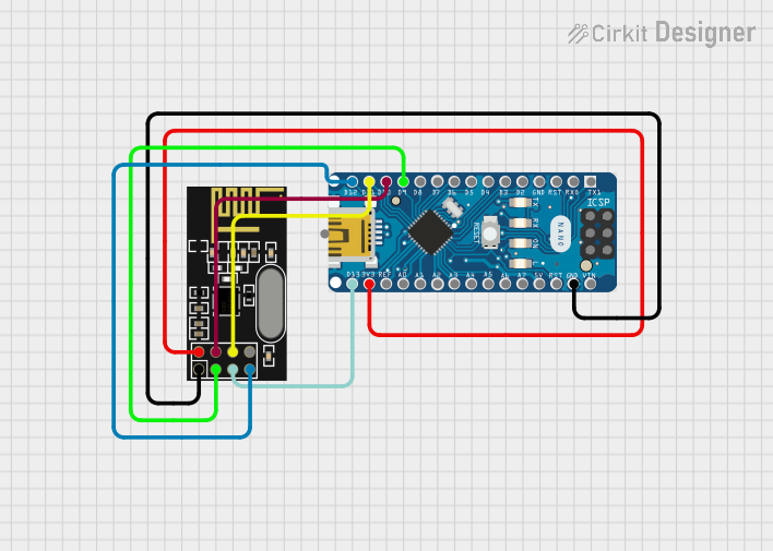
This document provides a detailed overview of a circuit that integrates an Arduino Nano microcontroller with an NRF24L01 wireless transceiver module. The purpose of this circuit is to enable wireless communication capabilities for the Arduino Nano using the NRF24L01 module. The circuit is designed to establish a Serial Peripheral Interface (SPI) connection between the two components, along with the necessary power connections.
Component List
Arduino Nano
- Description: A compact microcontroller board based on the ATmega328P, which is compatible with the Arduino software.
- Purpose: Acts as the central processing unit of the circuit, controlling the NRF24L01 module and executing the user-defined code.
- Pins: D1/TX, D0/RX, RESET, GND, D2, D3, D4, D5, D6, D7, D8, D9, D10, D11/MOSI, D12/MISO, VIN, 5V, A7, A6, A5, A4, A3, A2, A1, A0, AREF, 3V3, D13/SCK
NRF24L01
- Description: A 2.4GHz wireless transceiver module that enables wireless communication between devices.
- Purpose: To provide wireless communication capabilities when interfaced with the Arduino Nano.
- Pins: IRQ (not used), MOSI, CSN, VCC (3V), GND, CE, SCK, MISO
Wiring Details
Arduino Nano
- D11/MOSI: Connected to MOSI on NRF24L01 for SPI data transmission.
- D10: Connected to CSN on NRF24L01 to select the device on the SPI bus.
- 3V3: Provides power to VCC (3V) on NRF24L01.
- GND: Connected to GND on NRF24L01 for a common ground reference.
- D9: Connected to CE on NRF24L01 to enable the chip for communication.
- D13/SCK: Connected to SCK on NRF24L01 for SPI clock signal.
- D12/MISO: Connected to MISO on NRF24L01 for SPI data reception.
NRF24L01
- MOSI: Connected to D11/MOSI on Arduino Nano.
- CSN: Connected to D10 on Arduino Nano.
- VCC (3V): Powered by 3V3 from Arduino Nano.
- GND: Common ground with Arduino Nano.
- CE: Connected to D9 on Arduino Nano.
- SCK: Connected to D13/SCK on Arduino Nano.
- MISO: Connected to D12/MISO on Arduino Nano.
Documented Code
Arduino Nano Code (sketch.ino)
void setup() {
  // put your setup code here, to run once:

}

void loop() {
  // put your main code here, to run repeatedly:

}
This code template provides the basic structure for the Arduino sketch. The setup() function is intended to contain initialization code that runs once at the start, while the loop() function contains code that runs continuously in a loop. Users should add specific code to initialize the SPI interface and handle communication with the NRF24L01 module within these functions.