Cirkit Designer
Your all-in-one circuit design IDE
Home /
Project Documentation
ESP32-Based Wi-Fi Controlled Robotic Car with OLED Display and Laser Shooting
Circuit Documentation
Summary
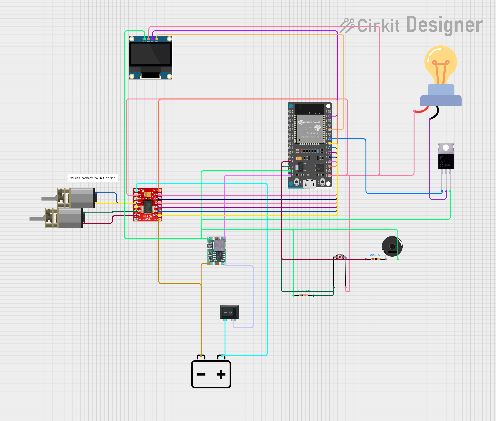
This circuit is designed to control a motorized system using an ESP32 microcontroller, a TB6612FNG motor driver, and various other components. The system includes a 0.96" OLED display for visual feedback, a piezo buzzer for audio alerts, and a laser controlled by a MOSFET. The circuit also features a photocell (LDR) for light detection and a rocker switch for power control. The ESP32 is programmed to interface with a PS3 controller for remote control of the motors and laser.
Component List
DC Mini Metal Gear Motor
- Description: A small DC motor with metal gears for increased torque.
- Pins: IN1, IN2
TB6612FNG Motor Driver
- Description: A dual motor driver capable of controlling two DC motors.
- Pins: GND, B01, B02, A02, A01, VCC, VM, PWMB, BI2, BI1, STBY, AI1, AI2, PWMA
0.96" OLED
- Description: A small OLED display for visual feedback.
- Pins: GND, VDD, SCK, SDA
ESP32 Devkit V1
- Description: A powerful microcontroller with Wi-Fi and Bluetooth capabilities.
- Pins: 3V3, GND, D15, D2, D4, RX2, TX2, D5, D18, D19, D21, RX0, TX0, D22, D23, EN, VP, VN, D34, D35, D32, D33, D25, D26, D27, D14, D12, D13, VIN
Mosfet
- Description: A transistor used for switching and amplifying electronic signals.
- Pins: Gate, Drain, Source
12v Battery
- Description: A power source providing 12V DC.
- Pins: +, -
Mini-360 DC-DC Step Down Buck Converter
- Description: A voltage regulator that steps down 12V to a lower voltage.
- Pins: Input -, Input +, Output +, Output -
LED bulb AC / Bombillo AC
- Description: An AC-powered LED bulb.
- Pins: +, -
Rocker Switch (SPST)
- Description: A single-pole single-throw switch for power control.
- Pins: 1, 2
Photocell (LDR)
- Description: A light-dependent resistor used for light detection.
- Pins: pin 0, pin 1
Piezo Buzzer
- Description: A small speaker used for audio alerts.
- Pins: pin 1, pin 2
Resistor (51k Ohms)
- Description: A resistor with a resistance of 51k Ohms.
- Pins: pin1, pin2
Resistor (220 Ohms)
- Description: A resistor with a resistance of 220 Ohms.
- Pins: pin1, pin2
Wiring Details
DC Mini Metal Gear Motor
- IN1 connected to B01 of TB6612FNG Motor Driver
- IN2 connected to B02 of TB6612FNG Motor Driver
TB6612FNG Motor Driver
- GND connected to - of 12v Battery and Input - of Mini-360 DC-DC Step Down Buck Converter
- B01 connected to IN1 of DC Mini Metal Gear Motor
- B02 connected to IN2 of DC Mini Metal Gear Motor
- A02 connected to IN1 of another DC Mini Metal Gear Motor
- A01 connected to IN2 of another DC Mini Metal Gear Motor
- VCC connected to 3V3 of ESP32 Devkit V1
- VM connected to 2 of Rocker Switch (SPST)
- PWMB connected to D5 of ESP32 Devkit V1
- BI2 connected to TX2 of ESP32 Devkit V1
- BI1 connected to RX2 of ESP32 Devkit V1
- STBY connected to 3V3 of ESP32 Devkit V1
- AI1 connected to D4 of ESP32 Devkit V1
- AI2 connected to D2 of ESP32 Devkit V1
- PWMA connected to D15 of ESP32 Devkit V1
0.96" OLED
- GND connected to GND of ESP32 Devkit V1
- VDD connected to 3V3 of ESP32 Devkit V1
- SCK connected to D22 of ESP32 Devkit V1
- SDA connected to D21 of ESP32 Devkit V1
ESP32 Devkit V1
- GND connected to GND of Piezo Buzzer, Source of Mosfet, pin1 of Resistor (51k Ohms), GND of 0.96" OLED, and Output - of Mini-360 DC-DC Step Down Buck Converter
- 3V3 connected to pin 1 of Photocell (LDR), STBY and VCC of TB6612FNG Motor Driver, + of LED bulb AC / Bombillo AC, and VDD of 0.96" OLED
- D22 connected to SCK of 0.96" OLED
- D21 connected to SDA of 0.96" OLED
- D5 connected to PWMB of TB6612FNG Motor Driver
- TX2 connected to BI2 of TB6612FNG Motor Driver
- RX2 connected to BI1 of TB6612FNG Motor Driver
- D4 connected to AI1 of TB6612FNG Motor Driver
- D2 connected to AI2 of TB6612FNG Motor Driver
- D15 connected to PWMA of TB6612FNG Motor Driver
- VIN connected to Output + of Mini-360 DC-DC Step Down Buck Converter
- D18 connected to Gate of Mosfet
- D12 connected to pin1 of Resistor (220 Ohms)
- D13 connected to pin 0 of Photocell (LDR) and pin2 of Resistor (51k Ohms)
Mosfet
- Gate connected to D18 of ESP32 Devkit V1
- Drain connected to - of LED bulb AC / Bombillo AC
- Source connected to GND of ESP32 Devkit V1
12v Battery
- + connected to 2 of Rocker Switch (SPST) and VM of TB6612FNG Motor Driver
- - connected to GND of TB6612FNG Motor Driver and Input - of Mini-360 DC-DC Step Down Buck Converter
Mini-360 DC-DC Step Down Buck Converter
- Input - connected to - of 12v Battery and GND of TB6612FNG Motor Driver
- Input + connected to 1 of Rocker Switch (SPST)
- Output + connected to VIN of ESP32 Devkit V1
- Output - connected to GND of ESP32 Devkit V1
LED bulb AC / Bombillo AC
- + connected to 3V3 of ESP32 Devkit V1
- - connected to Drain of Mosfet
Rocker Switch (SPST)
- 1 connected to Input + of Mini-360 DC-DC Step Down Buck Converter
- 2 connected to + of 12v Battery and VM of TB6612FNG Motor Driver
Photocell (LDR)
- pin 0 connected to D13 of ESP32 Devkit V1 and pin2 of Resistor (51k Ohms)
- pin 1 connected to 3V3 of ESP32 Devkit V1
Piezo Buzzer
- pin 1 connected to GND of ESP32 Devkit V1
- **