
Wi-Fi Controlled RGB LED Strip with Battery Management System
View and Edit Project In Cirkit Designer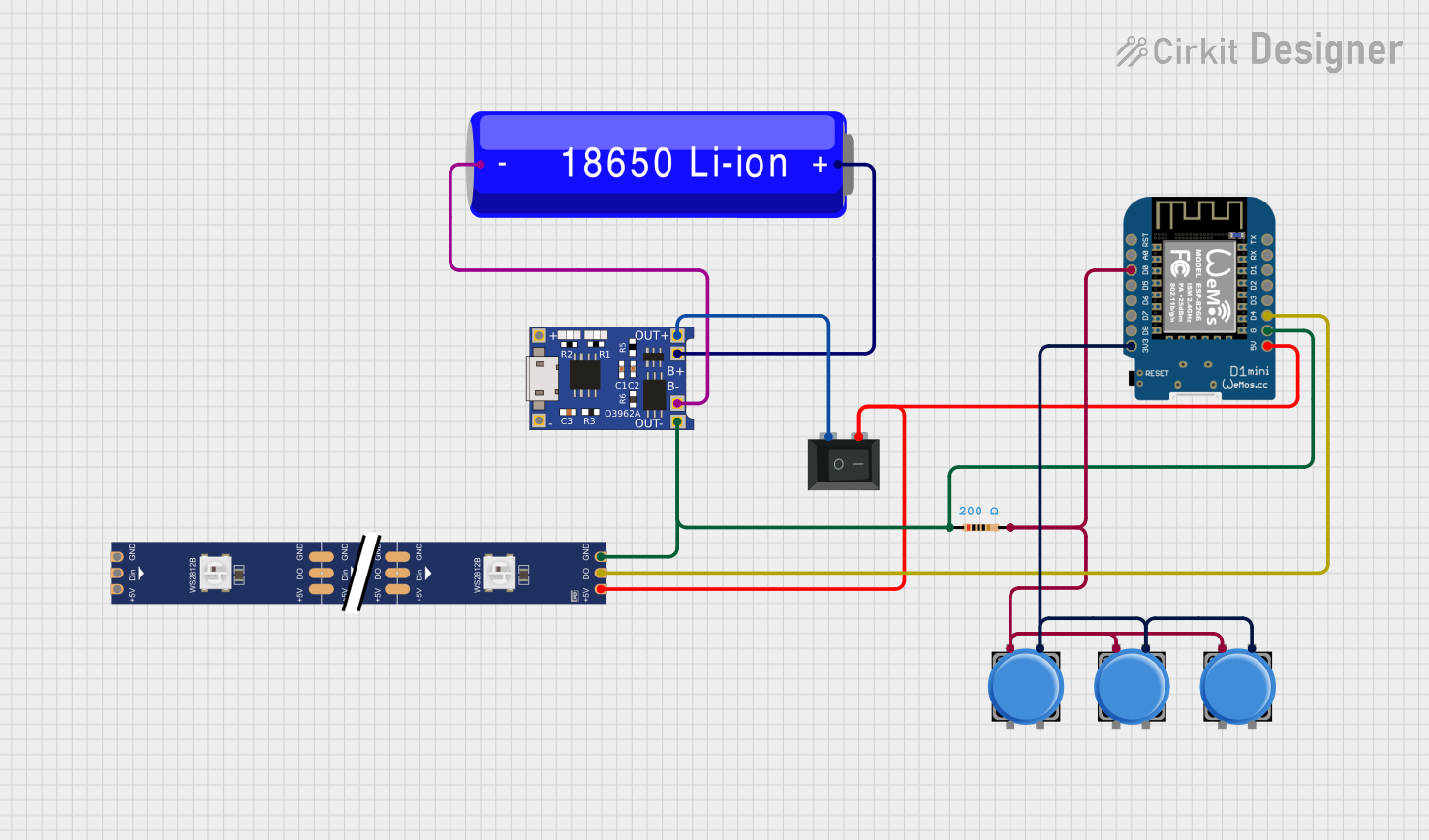
Circuit Documentation
Summary of the Circuit
This circuit appears to be a rechargeable LED lighting system using a Wemos D1 Mini microcontroller to control a WS2812 RGB LED strip. The system is powered by an 18650 Li-ion battery, which is charged through a TP4056 charging module. User interaction is facilitated through pushbuttons and a rocker switch that controls the power supply to the LED strip and the microcontroller.
Component List
Wemos D1 Mini
- Microcontroller board based on the ESP8266.
- Pins: RST, A0, D0, D5, D6, D7, D8, 3V3, 5V, G, D4, D3, D2, D1, RX, TX.
18650 Li-ion Battery
- Rechargeable battery commonly used in portable electronics.
- Pins: -, +.
TP4056
- A lithium battery charging module with battery protection.
- Pins: OUT-, B-, B+, OUT+, IN-, IN+.
Rocker Switch (SPST)
- A single-pole single-throw switch used to connect or disconnect the circuit.
- Pins: 1, 2.
Pushbutton
- A momentary switch that closes the circuit when pressed.
- Pins: Pin 2, Pin 1, Pin 3, Pin 4.
WS2812 RGB LED strip
- An addressable LED strip capable of displaying multiple colors.
- Pins: DIN, 5V, GND, DO.
Resistor (200 Ohms)
- A passive two-terminal electrical component used to limit current.
- Pins: pin1, pin2.
- Resistance: 200 Ohms.
Wiring Details
Wemos D1 Mini
- D0 connected to Pushbuttons (signal input).
- 3V3 connected to Pushbuttons (power supply).
- 5V connected to Rocker Switch and WS2812 RGB LED strip (power supply).
- G connected to TP4056 OUT- and WS2812 RGB LED strip GND (ground).
- D4 connected to WS2812 RGB LED strip DIN (data input).
18650 Li-ion Battery
-
- (negative) connected to TP4056 B- (battery negative).
-
- (positive) connected to TP4056 B+ (battery positive).
TP4056
- OUT- connected to Resistor pin1 and Wemos D1 Mini G (ground).
- B- connected to 18650 Li-ion Battery - (battery negative).
- B+ connected to 18650 Li-ion Battery + (battery positive).
- OUT+ connected to Rocker Switch.
Rocker Switch (SPST)
- Pin 1 connected to TP4056 OUT+ (power input from charging module).
- Pin 2 connected to Wemos D1 Mini 5V and WS2812 RGB LED strip 5V (power output to microcontroller and LED strip).
Pushbuttons
- Pin 1 connected to Wemos D1 Mini D0 (signal input from buttons).
- Pin 3 connected to Wemos D1 Mini 3V3 (power supply to buttons).
WS2812 RGB LED strip
- DIN connected to Wemos D1 Mini D4 (data input from microcontroller).
- 5V connected to Rocker Switch (power supply).
- GND connected to Wemos D1 Mini G (ground).
- DO not connected (data output, for chaining additional LED strips).
Resistor (200 Ohms)
- Pin 1 connected to TP4056 OUT- (ground).
- Pin 2 connected to Pushbuttons (current limiting for button signal).
Documented Code
There is no code provided for the microcontroller. The expected code would typically initialize the GPIO pins, set up the Wi-Fi connection if needed, and include a library for controlling the WS2812 RGB LED strip. It would also include routines to read the pushbutton states and send corresponding commands to the LED strip to change colors, patterns, or turn on/off based on user input.