Cirkit Designer
Your all-in-one circuit design IDE
Home /
Project Documentation
Arduino Nano Controlled Dual Motor Driver Circuit with Buck Converter Power Management
Circuit Documentation
Summary
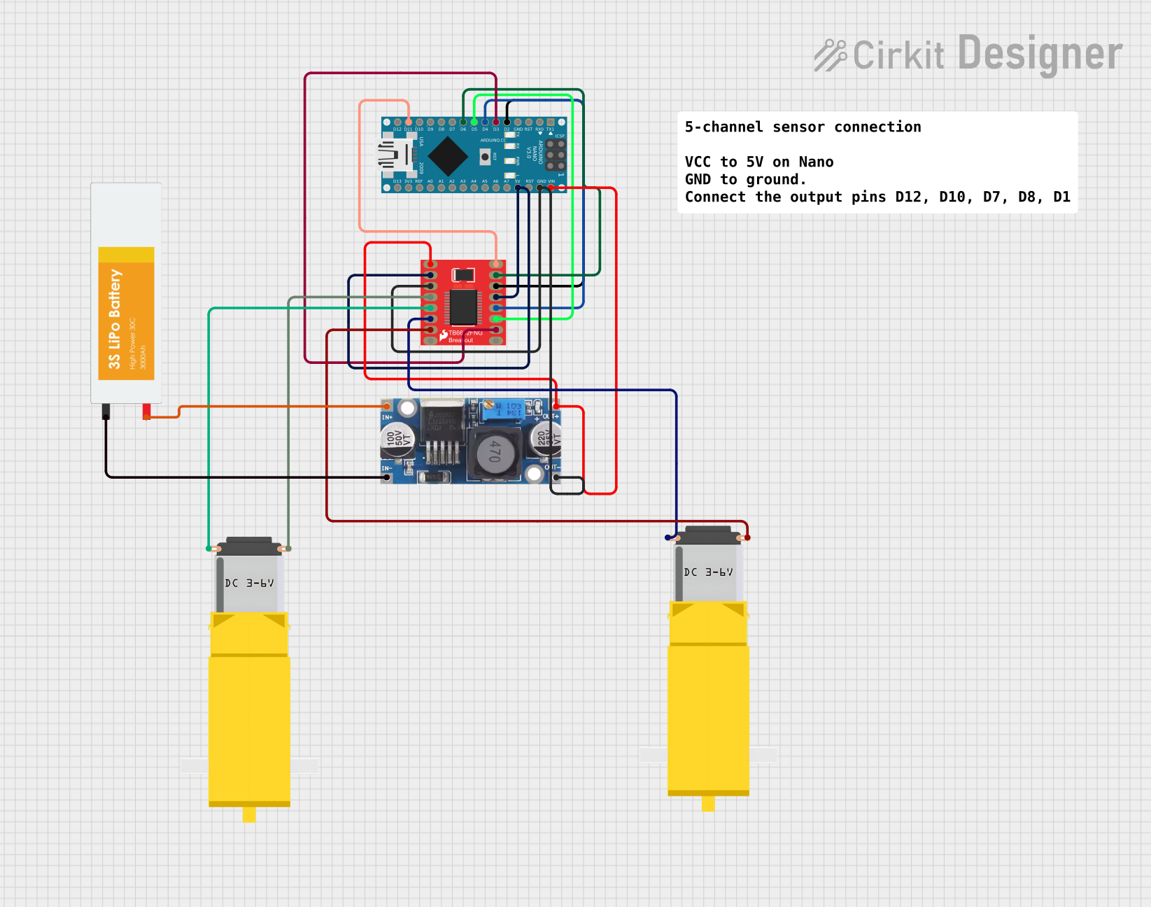
This circuit integrates an Arduino Nano microcontroller with a Motor Driver 1A Dual TB6612FNG to control two DC gearmotors. A step-down buck converter is used to regulate the voltage supplied by a LiPo battery to the appropriate levels for the Arduino and the motor driver. The Arduino Nano is programmed to interface with the motor driver, which in turn drives the gearmotors based on the signals received from the Arduino.
Component List
Arduino Nano
- Microcontroller board based on the ATmega328P
- Offers a variety of digital and analog I/O pins
- Can be powered via USB or an external power supply
Motor Driver 1A Dual TB6612FNG
- Dual motor driver capable of driving a pair of DC motors
- Supports up to 1A per channel
- Requires a power supply for the motors and a separate VCC for logic
Step-down Buck Converter
- Converts higher input voltage to a lower output voltage
- Ensures that the Arduino and motor driver receive the correct operating voltage
Gearmotor DC / Motorreductor
- Two DC gearmotors used for motion
- Operated by the motor driver
LiPo Battery
- Provides power to the circuit
- High energy density and rechargeable
Comment
- A placeholder for additional notes or comments about the circuit
Wiring Details
Arduino Nano
D2connected to Motor Driver AIN1D3connected to Motor Driver PWMBD4connected to Motor Driver BIN1D5connected to Motor Driver BIN2D6connected to Motor Driver AIN2D11/MOSIconnected to Motor Driver PWMAVINconnected to Buck Converter OUT + and Motor Driver VMGNDconnected to Buck Converter OUT - GND and Motor Driver GND5Vconnected to Motor Driver STBY and VCC
Motor Driver 1A Dual TB6612FNG
B01connected to Gearmotor 1 Pin1B02connected to Gearmotor 1 Pin2A02connected to Gearmotor 2 Pin2A01connected to Gearmotor 2 Pin1
Step-down Buck Converter
IN +connected to LiPo Battery VCCIN - GNDconnected to LiPo Battery GND
Gearmotor DC / Motorreductor 1
Pin1connected to Motor Driver B01Pin2connected to Motor Driver B02
Gearmotor DC / Motorreductor 2
Pin1connected to Motor Driver A01Pin2connected to Motor Driver A02
LiPo Battery
VCCconnected to Buck Converter IN +GNDconnected to Buck Converter IN - GND
Documented Code
Arduino Nano Code (sketch.ino)
void setup() {
  // put your setup code here, to run once:

}

void loop() {
  // put your main code here, to run repeatedly:

}
Additional Notes (documentation.txt)
No additional code documentation provided.