Arduino-Controlled LED Lighting System with Ultrasonic Sensors

Circuit Documentation
Summary
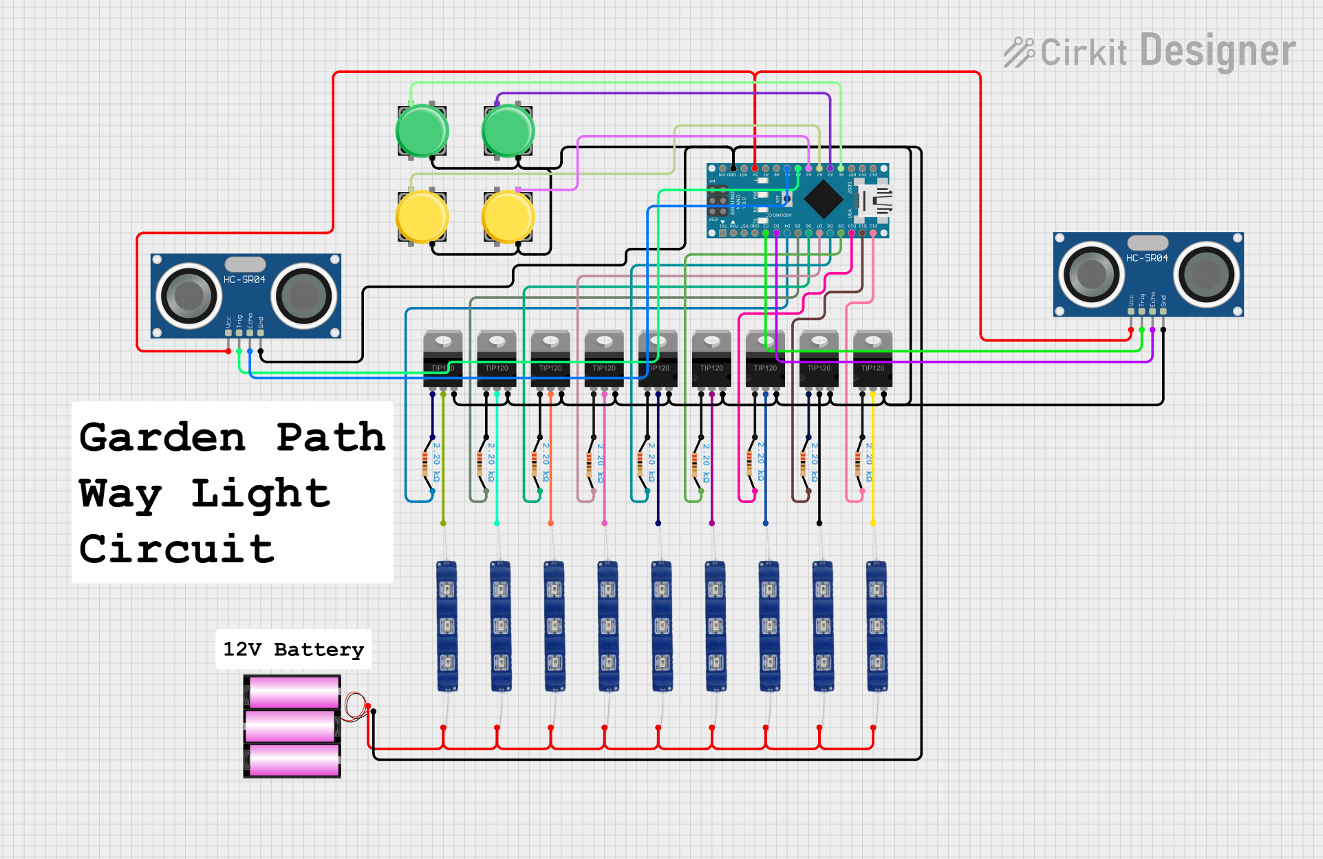
This circuit is designed to control multiple 12V blue LEDs using TIP120 high-current Darlington transistors, which are driven by an Arduino Nano microcontroller. The circuit includes pushbuttons for user input and HC-SR04 ultrasonic sensors for distance measurement. The LEDs are connected to the collectors of the transistors, and the emitters of all transistors are tied together and connected to the ground. Each transistor's base is connected to the Arduino through a 2.2k Ohm resistor, allowing the microcontroller to switch the LEDs on and off. The ultrasonic sensors are powered by the 5V output from the Arduino and are interfaced with digital pins for triggering and echo reception. The pushbuttons are connected to analog input pins for additional control functionality.
Component List
Microcontroller
- Arduino Nano: A compact microcontroller board based on the ATmega328P, equipped with a variety of digital and analog I/O pins.
Transistors
- TIP120 Hi-Current Darlington Transistors: Used to switch high-current loads such as the 12V LEDs.
Resistors
- 2.2k Ohm Resistors: Limit the current flowing into the base of the Darlington transistors from the Arduino's digital output pins.
LEDs
- 12V Blue LEDs: High-voltage LEDs that emit blue light when powered.
Sensors
- HC-SR04 Ultrasonic Sensors: Measure distances by emitting ultrasonic waves and measuring the time taken for the echo to return.
Power Supply
- Battery 12V: Provides the necessary power to drive the 12V LEDs.
User Input
- Pushbuttons: Allow user interaction with the circuit, providing control signals to the Arduino.
Wiring Details
Arduino Nano
- Digital pins D2 to D12/MISO are connected to the base resistors of the Darlington transistors.
- Analog pins A0 to A5 are used for pushbutton inputs and interfacing with the ultrasonic sensors.
- The 5V pin provides power to the ultrasonic sensors.
- The GND pin is connected to the common emitter of the Darlington transistors and the ground pins of the ultrasonic sensors.
TIP120 Hi-Current Darlington Transistors
- BASE: Connected to the Arduino digital pins through 2.2k Ohm resistors.
- COLLECTOR: Connected to the ground pin of the corresponding 12V LED.
- EMITTER: Commonly connected to the ground.
2.2k Ohm Resistors
- One end connected to the Arduino digital pins (D4 to D12/MISO).
- The other end connected to the base of the corresponding Darlington transistor.
12V Blue LEDs
- VCC: All connected to the positive terminal of the 12V battery.
- GND: Connected to the collector of the corresponding Darlington transistor.
HC-SR04 Ultrasonic Sensors
- VCC: Connected to the 5V output of the Arduino.
- TRIG: Connected to digital pins D2 and A4 of the Arduino.
- ECHO: Connected to digital pins D3 and A5 of the Arduino.
- GND: Connected to the common ground.
Pushbuttons
- One side (Pin 1) connected to the analog input pins A0 to A3 of the Arduino.
- The other side (Pin 4) connected to the common ground.
Battery 12V
- Positive terminal (+): Connected to the VCC pins of all 12V LEDs.
- Negative terminal (-): Connected to the common ground.
Documented Code
Arduino Nano Code (sketch.ino)
void setup() {
  // put your setup code here, to run once:

}

void loop() {
  // put your main code here, to run repeatedly:

}
Additional Notes (documentation.txt)
No additional code documentation was provided.