
ESP32-CAM and ESP32 DEVKIT V1 Controlled Multi-Servo System with Power Regulation
View and Edit Project In Cirkit Designer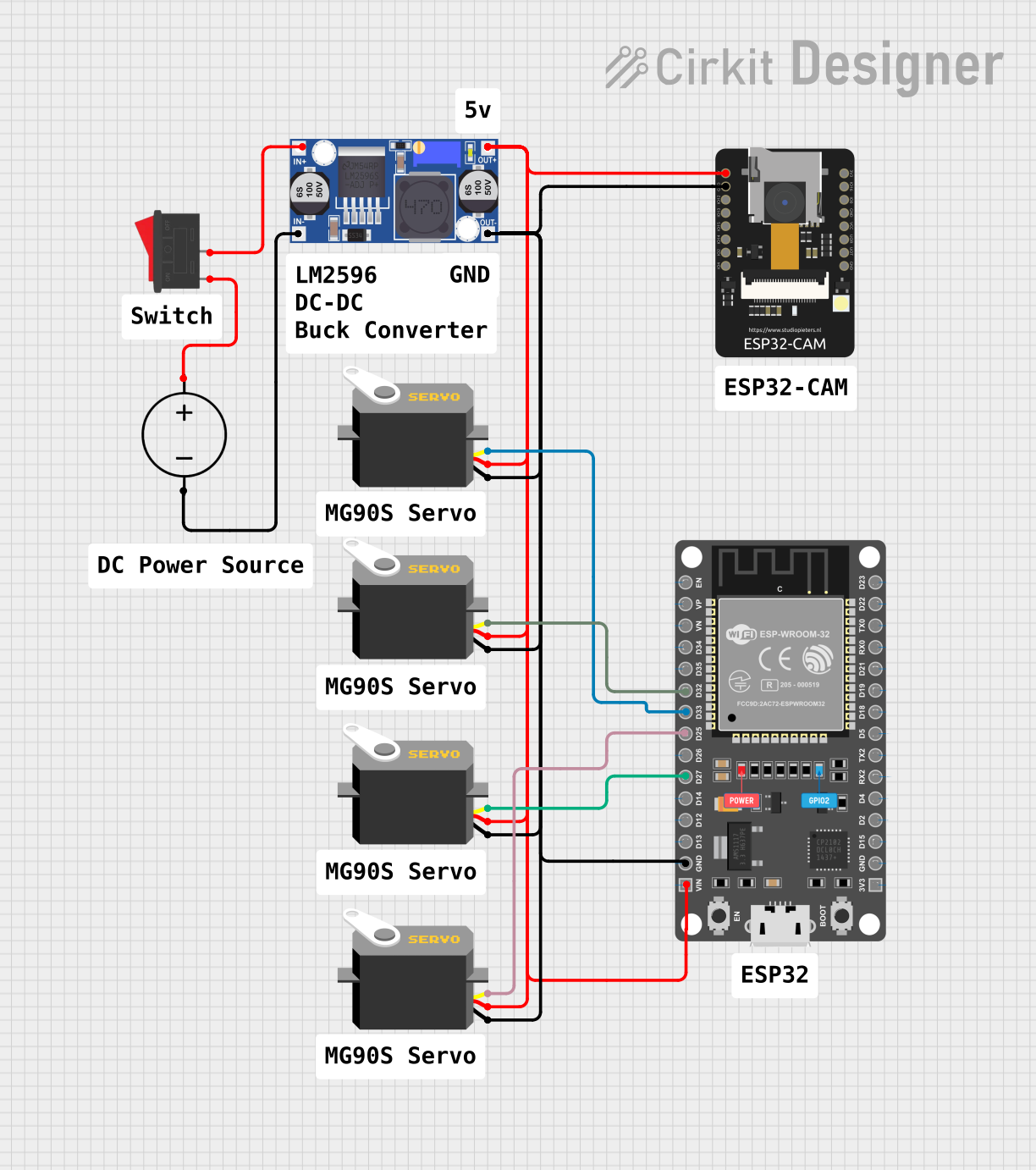
Circuit Documentation
Summary
The circuit in question appears to be designed for controlling multiple servo motors using two microcontroller units (MCUs): an ESP32-CAM and an ESP32 DEVKIT V1 (30 pins). The circuit includes a power management system with a DC power source, a buck converter for voltage regulation, and a rocker switch for power control. The servos are powered and controlled by the ESP32 DEVKIT V1, which likely sends PWM signals to the servos' control lines.
Component List
Microcontrollers
- ESP32-CAM: A microcontroller with camera functionality, capable of Wi-Fi and Bluetooth communication.
- ESP32 DEVKIT V1 (30 pins): A development board with an ESP32 microcontroller, suitable for IoT projects with a variety of GPIO pins.
Power Management
- DC Power Source: Provides the input voltage for the circuit.
- Buck Converter: Steps down the voltage from the DC Power Source to a lower level suitable for the microcontrollers and servos.
- Rocker Switch: Acts as an on/off switch for the circuit.
Actuators
- Servo (x4): Actuators that can be precisely controlled using PWM signals for various positioning applications.
Miscellaneous
- Comment (x10): Placeholder components that may represent annotations or notes within the circuit design.
Wiring Details
ESP32-CAM
- 5V: Connected to the 5V output from the Buck Converter.
- GND: Connected to the ground plane of the circuit.
ESP32 DEVKIT V1 (30 pins)
- VIN: Connected to the 5V output from the Buck Converter.
- GND: Connected to the ground plane of the circuit.
- D25, D27, D32, D33: Connected to the pulse pins of the four servos, likely used for PWM control signals.
Servos
- vcc (x4): Connected to the 5V output from the Buck Converter.
- gnd (x4): Connected to the ground plane of the circuit.
- pulse (x4): Each connected to a different GPIO pin on the ESP32 DEVKIT V1 for control.
Buck Converter
- IN+: Connected to the positive output of the Rocker Switch.
- IN-: Connected to the ground of the DC Power Source.
- OUT+: Connected to the 5V power rail of the circuit.
- OUT-: Connected to the ground plane of the circuit.
DC Power Source
- Positive: Connected to the input of the Rocker Switch.
- Ground: Connected to the ground plane of the circuit.
Rocker Switch
- 1: Connected to the positive terminal of the DC Power Source.
- 2: Connected to the input of the Buck Converter.
Documented Code
No code has been provided for the microcontrollers in the circuit. For a complete documentation, the code that runs on the ESP32-CAM and ESP32 DEVKIT V1 should be included, detailing how the servos are controlled and how the camera functionality is managed.