
Arduino UNO-Based Automated Water Level Monitoring and Pump Control System
View and Edit Project In Cirkit Designer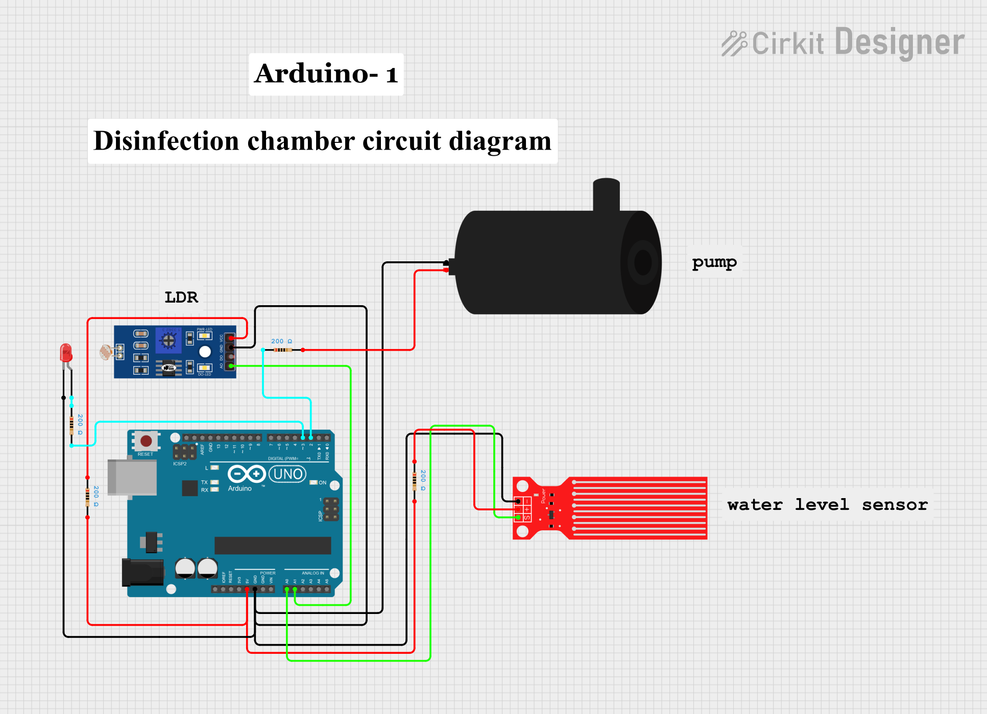
Circuit Documentation
Summary
This document provides a detailed overview of a circuit that includes an Arduino UNO microcontroller, various sensors, a water pump, an LED, and several resistors. The circuit is designed to interface with a water level sensor and an LDR (Light Dependent Resistor) to control a water pump and an LED. The Arduino UNO serves as the central control unit, processing sensor data and controlling the output devices.
Component List
Arduino UNO
- Description: A microcontroller board based on the ATmega328P.
- Pins: UNUSED, IOREF, Reset, 3.3V, 5V, GND, Vin, A0, A1, A2, A3, A4, A5, SCL, SDA, AREF, D13, D12, D11, D10, D9, D8, D7, D6, D5, D4, D3, D2, D1, D0
Water Level Sensor
- Description: A sensor used to detect the level of water.
- Pins: SIG, VCC, GND
Water Pump
- Description: A device used to pump water.
- Pins: positive, negative
LDR (Light Dependent Resistor)
- Description: A resistor whose resistance decreases with increasing incident light intensity.
- Pins: A0, D0, GND, VCC
LED: Two Pin (red)
- Description: A red LED with two pins.
- Pins: cathode, anode
Resistor
- Description: A passive electrical component with a resistance of 200 Ohms.
- Pins: pin1, pin2
Comment
- Description: Placeholder for comments in the circuit.
- Pins: None
Wiring Details
Arduino UNO
5V is connected to:
- Resistor (pin2)
- Resistor (pin2)
GND is connected to:
- Water Pump (negative)
- LED (cathode)
- LDR (GND)
- Water Level Sensor (GND)
A0 is connected to:
- Water Level Sensor (SIG)
A1 is connected to:
- LDR (A0)
D2 is connected to:
- Resistor (pin1)
D3 is connected to:
- Resistor (pin2)
Water Level Sensor
SIG is connected to:
- Arduino UNO (A0)
VCC is connected to:
- Resistor (pin1)
GND is connected to:
- Arduino UNO (GND)
Water Pump
positive is connected to:
- Resistor (pin2)
negative is connected to:
- Arduino UNO (GND)
LDR
A0 is connected to:
- Arduino UNO (A1)
GND is connected to:
- Arduino UNO (GND)
VCC is connected to:
- Resistor (pin1)
LED: Two Pin (red)
cathode is connected to:
- Arduino UNO (GND)
anode is connected to:
- Resistor (pin1)
Resistor
pin1 is connected to:
- Arduino UNO (D2)
- Water Pump (positive)
- LDR (VCC)
- LED (anode)
- Water Level Sensor (VCC)
pin2 is connected to:
- Arduino UNO (5V)
- Arduino UNO (5V)
- Arduino UNO (D3)
- Water Pump (positive)
Documented Code
Arduino UNO Code (sketch.ino)
void setup() {
  // put your setup code here, to run once:

}

void loop() {
  // put your main code here, to run repeatedly:

}
Documentation (documentation.txt)
This document provides a comprehensive overview of the circuit, including a summary, component list, wiring details, and documented code. The Arduino UNO serves as the central control unit, interfacing with various sensors and controlling output devices such as the water pump and LED.