
ESP32-Based Smart Energy Monitoring System with LCD Display and Sensors
View and Edit Project In Cirkit Designer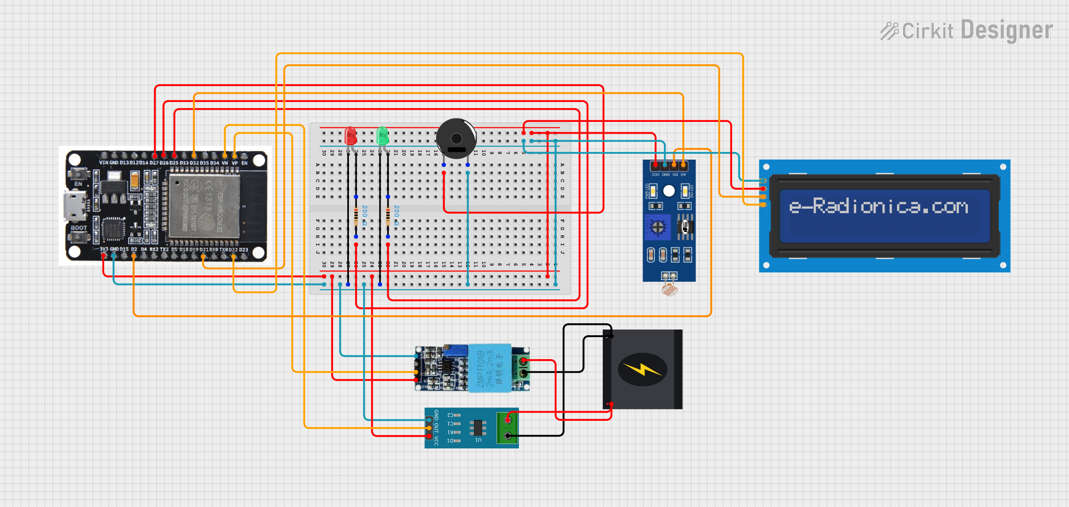
Circuit Documentation
Summary
This document provides a detailed overview of a circuit that includes an ESP32 microcontroller, various sensors (voltage, current, and light), LEDs, a piezo buzzer, an LCD screen, and a 240V power source. The circuit is designed to monitor and display various parameters, and it includes code for the ESP32 microcontroller.
Component List
ESP32
- Description: A powerful microcontroller with Wi-Fi and Bluetooth capabilities.
- Pins: EN, VP, VN, D34, D35, D32, D33, D25, D26, D27, D14, D12, D13, GND, VIN, 3V3, D15, D2, D4, RX2, TX2, D5, D18, D19, D21, RX0, TX0, D22, D23, BOOT
Voltage Sensor
- Description: A sensor used to measure voltage levels.
- Pins: Ground, Phase, Vcc, Out, Gnd
Current Sensor 5A
- Description: A sensor used to measure current up to 5A.
- Pins: 1, 2, GND, OUT, VCC
LED: Two Pin (green)
- Description: A green LED with two pins.
- Pins: cathode, anode
LED: Two Pin (red)
- Description: A red LED with two pins.
- Pins: cathode, anode
Resistor (200 Ohms)
- Description: A resistor with a resistance of 200 Ohms.
- Pins: pin1, pin2
Piezo Buzzer
- Description: A piezoelectric buzzer used for sound output.
- Pins: pin 1, pin 2
LDR
- Description: A light-dependent resistor used to measure light intensity.
- Pins: A0, D0, GND, VCC
LCD screen 16x2 I2C
- Description: A 16x2 character LCD screen with I2C interface.
- Pins: SCL, SDA, VCC, GND
240V Power Source
- Description: A power source providing 240V AC.
- Pins: Live, Neutral
Wiring Details
ESP32
GND is connected to:
- Piezo Buzzer pin 2
- LED (green) cathode
- LED (red) cathode
- Current Sensor 5A GND
- Voltage Sensor Gnd
- LDR GND
- LCD screen 16x2 I2C GND
D27 is connected to Piezo Buzzer pin 1
D25 is connected to Resistor pin2
D26 is connected to Resistor pin2
3V3 is connected to:
- LDR VCC
- LCD screen 16x2 I2C VCC
- Current Sensor 5A VCC
- Voltage Sensor Vcc
VP is connected to Voltage Sensor Out
VN is connected to Current Sensor 5A OUT
D32 is connected to LDR A0
D2 is connected to LDR D0
D21 is connected to LCD screen 16x2 I2C SDA
D22 is connected to LCD screen 16x2 I2C SCL
Voltage Sensor
- Ground is connected to 240V Power Source Neutral
- Phase is connected to 240V Power Source Live
- Vcc is connected to ESP32 3V3
- Out is connected to ESP32 VP
- Gnd is connected to ESP32 GND
Current Sensor 5A
- 1 is connected to 240V Power Source Neutral
- 2 is connected to 240V Power Source Live
- GND is connected to ESP32 GND
- OUT is connected to ESP32 VN
- VCC is connected to ESP32 3V3
LED: Two Pin (green)
- cathode is connected to ESP32 GND
- anode is connected to Resistor pin1
LED: Two Pin (red)
- cathode is connected to ESP32 GND
- anode is connected to Resistor pin1
Resistor (200 Ohms)
- pin1 is connected to LED (green) anode
- pin2 is connected to ESP32 D25
Resistor (200 Ohms)
- pin1 is connected to LED (red) anode
- pin2 is connected to ESP32 D26
Piezo Buzzer
- pin 1 is connected to ESP32 D27
- pin 2 is connected to ESP32 GND
LDR
- A0 is connected to ESP32 D32
- D0 is connected to ESP32 D2
- GND is connected to ESP32 GND
- VCC is connected to ESP32 3V3
LCD screen 16x2 I2C
- SCL is connected to ESP32 D22
- SDA is connected to ESP32 D21
- VCC is connected to ESP32 3V3
- GND is connected to ESP32 GND
240V Power Source
Live is connected to:
- Voltage Sensor Phase
- Current Sensor 5A 2
Neutral is connected to:
- Voltage Sensor Ground
- Current Sensor 5A 1
Documented Code
ESP32 Code (sketch.ino)
void setup() {
  // put your setup code here, to run once:

}

void loop() {
  // put your main code here, to run repeatedly:

}
Documentation (documentation.txt)
This document provides a comprehensive overview of the circuit, including a summary, component list, wiring details, and documented code.