
Arduino UNO Based Automated Pill Dispenser with GSM Notifications and RTC Scheduling
View and Edit Project In Cirkit Designer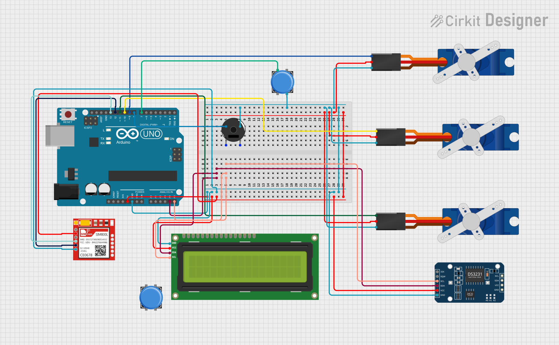
Circuit Documentation
Summary
This circuit is designed to operate as a medical pill dispenser with a real-time clock (RTC) for timekeeping, an LCD for user interface, servos for dispensing pills, a GSM module for sending SMS alerts, and a buzzer for audible notifications. The Arduino UNO serves as the central microcontroller, interfacing with the various components to control the dispensing mechanism and communicate with the user.
Component List
Arduino UNO
- Microcontroller board based on the ATmega328P
- Provides digital and analog I/O pins
- Used for controlling the overall operation of the circuit
DS3231 RTC
- Highly accurate I2C real-time clock
- Maintains timekeeping with a battery backup
- Used for scheduling pill dispensing events
Tower Pro SG90 Servo (x3)
- Small and lightweight servo motor
- Provides precise control of angular position
- Used to actuate the pill dispensing mechanism
I2C LCD 16x2 Screen
- Alphanumeric liquid crystal display
- I2C interface for reduced pin usage
- Displays time and user messages
Sim800l
- GSM/GPRS module
- Allows sending SMS messages for alerts and confirmations
- Interfaces with the Arduino via serial communication
Piezo Buzzer
- Electronic buzzer for producing sound
- Used for audible alerts and reminders
Pushbutton (x2)
- Simple tactile switch
- Used for user input to confirm actions
Wiring Details
Arduino UNO
5VandGNDare used to power the connected components.A4 (SDA)andA5 (SCL)are connected to the I2C bus for communication with the RTC and LCD.- Digital pins
D8,D7,D9,D10,D11,D12, andD13are used to interface with the buzzer, buttons, servos, and GSM module.
DS3231 RTC
SCLandSDAfor I2C communication with the Arduino.VCCandGNDfor power supply.
Tower Pro SG90 Servo
Signalpin connected to a designated digital pin on the Arduino for control signals.+5VandGNDfor power supply.
I2C LCD 16x2 Screen
SCLandSDAfor I2C communication with the Arduino.VCC (5V)andGNDfor power supply.
Sim800l
RXDandTXDconnected to digital pins on the Arduino for serial communication.VCCandGNDfor power supply.
Piezo Buzzer
- One pin connected to a digital pin on the Arduino for control signals.
- The other pin connected to
GND.
Pushbutton
- One pin connected to a digital pin on the Arduino for input signals.
- The other pin connected to
GND.
Documented Code
#include <Wire.h>
#include <LiquidCrystal_I2C.h>
#include <Servo.h>
#include <DS3231.h>
#include <SoftwareSerial.h>

// Pin definitions
#define BUZZER_PIN 8
#define BUTTON_PIN 7
#define SERVO_PIN_1 9
#define SERVO_PIN_2 10
#define SERVO_PIN_3 11

// GSM Module pins
#define GSM_TX 12
#define GSM_RX 13

// Servo and RTC objects
Servo pillServo1;
Servo pillServo2;
Servo pillServo3;
DS3231 rtc;
LiquidCrystal_I2C lcd(0x27, 16, 2);  // Adjust the address if needed

// GSM module
SoftwareSerial gsm(GSM_TX, GSM_RX);

// Variables
bool pillTaken = false;
int dispensingHour[3] = {8, 14, 20}; // Hardcoded times: 8 AM, 2 PM, 8 PM

void setup() {
  // Setup the servos
  pillServo1.attach(SERVO_PIN_1);
  pillServo2.attach(SERVO_PIN_2);
  pillServo3.attach(SERVO_PIN_3);

  // Setup the LCD
  lcd.begin();
  lcd.backlight();

  // Setup the RTC
  rtc.begin();

  // Setup the GSM module
  gsm.begin(9600);
  delay(1000); // Allow time for GSM module to initialize
  sendSMS("Medical dispenser started.");

  // Setup the buzzer and button
  pinMode(BUZZER_PIN, OUTPUT);
  pinMode(BUTTON_PIN, INPUT_PULLUP);
}

void loop() {
  DateTime now = rtc.now();
  lcd.setCursor(0, 0);
  lcd.print("Time: ");
  lcd.print(now.hour());
  lcd.print(":");
  lcd.print(now.minute());

  for (int i = 0; i < 3; i++) {
    if (now.hour() == dispensingHour[i] && now.minute() == 0 && !pillTaken) {
      dispensePill(i);
      pillTaken = true;
      sendSMS("Pills dispensed. Please take them.");
      startReminderTimer();
    }
  }

  // Reset pillTaken at the end of the hour
  if (now.minute() > 0) {
    pillTaken = false;
  }

  // Manual pill-taking confirmation
  if (digitalRead(BUTTON_PIN) == LOW) {
    pillTaken = true;
    lcd.setCursor(0, 1);
    lcd.print("Pill Taken       ");
    sendSMS("Pill taken confirmation received.");
    delay(1000);
  }

  delay(1000); // Loop every second
}

void dispensePill(int timeSlot) {
  if (timeSlot == 0) {
    pillServo1.write(90); // Adjust this value according to the dispenser mechanism
    delay(1000); // Wait for the pill to be dispensed
    pillServo1.write(0); // Return to original position
  } else if (timeSlot == 1) {
    pillServo2.write(90);
    delay(1000);
    pillServo2.write(0);
  } else if (timeSlot == 2) {
    pillServo3.write(90);
    delay(1000);
    pillServo3.write(0);
  }

  lcd.setCursor(0, 1);
  lcd.print("Pill Dispensed   ");
}

void sendSMS(String message) {
  gsm.print("AT+CMGF=1\r"); // Set SMS to text mode
  delay(100);
  gsm.print("AT+CMGS=\"+1234567890\"\r"); // Replace with your phone number
  delay(100);
  gsm.print(message);
  delay(100);
  gsm.write(26); // Send SMS (CTRL+Z)
  delay(1000);
}

void startReminderTimer() {
  long reminderTime = millis() + 600000; // 10 minutes reminder timer
  while (millis() < reminderTime) {
    if (pillTaken) return; // Exit if pill taken
    if (millis() >= reminderTime) {
      tone(BUZZER_PIN, 1000, 2000); // Buzzer alert
      sendSMS("Reminder: Please take your pills.");
    }
  }
}
This code is responsible for controlling the medical pill dispenser. It initializes the servos, LCD, RTC, and GSM module in the setup() function. The loop() function checks the current time against predefined dispensing hours and actuates the corresponding servo to dispense pills. It also listens for button presses to confirm pill intake and sends SMS alerts for various events. The sendSMS() function is used to send text messages, and startReminderTimer() sets up a reminder for the user to take their medication.