Cirkit Designer
Your all-in-one circuit design IDE
Home /
Project Documentation
Battery-Powered LED Circuit with Rocker Switch Control
Circuit Documentation
Summary
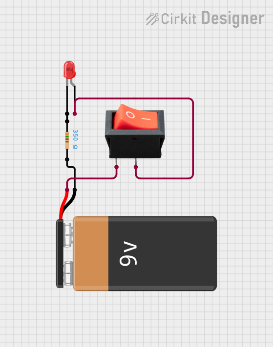
This document provides a detailed description of a simple electronic circuit consisting of a 9V battery, a rocker switch, a resistor, and a red LED. The circuit is designed to light up the LED when the switch is turned on. The resistor is used to limit the current flowing through the LED to prevent damage.
Component List
Resistor
- Description: A passive electrical component that limits the flow of electric current.
- Pins: pin1, pin2
- Properties:
- Resistance: 350 Ohms
LED: Two Pin (red)
- Description: A light-emitting diode that emits red light when current flows through it.
- Pins: cathode, anode
9V Battery
- Description: A power source providing 9 volts of direct current (DC).
- Pins: -, +
Rocker Switch
- Description: A switch that can open or close an electrical circuit.
- Pins: output, input
Wiring Details
Resistor
- Pin1 is connected to the cathode of the LED: Two Pin (red).
- Pin2 is connected to the negative (-) terminal of the 9V Battery.
LED: Two Pin (red)
- Cathode is connected to pin1 of the Resistor.
- Anode is connected to the output of the Rocker Switch.
9V Battery
- Negative (-) terminal is connected to pin2 of the Resistor.
- Positive (+) terminal is connected to the input of the Rocker Switch.
Rocker Switch
- Output is connected to the anode of the LED: Two Pin (red).
- Input is connected to the positive (+) terminal of the 9V Battery.
Code
There is no microcontroller code associated with this circuit.