Cirkit Designer
Your all-in-one circuit design IDE
Home /
Project Documentation
Arduino and ESP8266 Nodemcu Based Keypad Security System with Email Notifications
Circuit Documentation
Summary
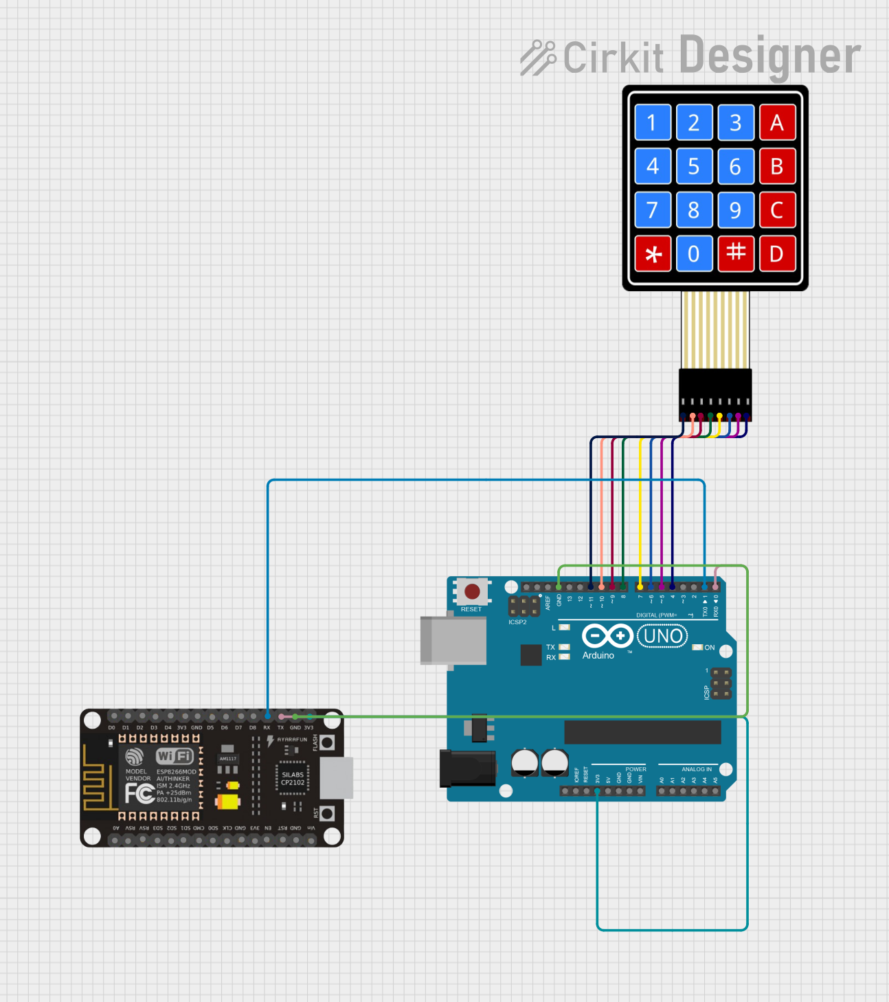
The circuit in question consists of an Arduino UNO, a 4x4 Membrane Matrix Keypad, and an ESP8266 NodeMCU microcontroller. The Arduino UNO is used as the primary controller, interfacing with the keypad for user input and communicating with the ESP8266 NodeMCU for wireless capabilities. The ESP8266 NodeMCU is programmed to handle WiFi connectivity and send email notifications based on certain triggers from the Arduino UNO. The keypad provides a user interface for password input and system interaction.
Component List
Arduino UNO
- Description: A microcontroller board based on the ATmega328P.
- Purpose: Acts as the main controller for the keypad and communicates with the ESP8266 NodeMCU.
4X4 Membrane Matrix Keypad
- Description: A simple interface for user input, consisting of 16 buttons arranged in a 4x4 grid.
- Purpose: Allows the user to input commands and passwords.
ESP8266 NodeMCU
- Description: A low-cost Wi-Fi microchip with full TCP/IP stack and microcontroller capability.
- Purpose: Provides wireless communication capabilities and sends email alerts.
Wiring Details
Arduino UNO
- 3.3V connected to ESP8266 NodeMCU 3V3
- GND connected to ESP8266 NodeMCU GND
- D11 connected to Keypad R1
- D10 connected to Keypad R2
- D9 connected to Keypad R3
- D8 connected to Keypad R4
- D7 connected to Keypad C1
- D6 connected to Keypad C2
- D5 connected to Keypad C3
- D4 connected to Keypad C4
- D1 (TX) connected to ESP8266 NodeMCU RX
- D0 (RX) connected to ESP8266 NodeMCU TX
4X4 Membrane Matrix Keypad
- R1 connected to Arduino UNO D11
- R2 connected to Arduino UNO D10
- R3 connected to Arduino UNO D9
- R4 connected to Arduino UNO D8
- C1 connected to Arduino UNO D7
- C2 connected to Arduino UNO D6
- C3 connected to Arduino UNO D5
- C4 connected to Arduino UNO D4
ESP8266 NodeMCU
- 3V3 connected to Arduino UNO 3.3V
- GND connected to Arduino UNO GND
- RX connected to Arduino UNO D1 (TX)
- TX connected to Arduino UNO D0 (RX)
Documented Code
Arduino UNO Code
#include <Keypad.h>
#include <Wire.h>
#include <SoftwareSerial.h>

char hexaKeys[4][4] = {
  {'1', '2', '3', 'A'},
  {'4', '5', '6', 'B'},
  {'7', '8', '9', 'C'},
  {'*', '0', '#', 'D'}
};
byte rowPins[4] = {11, 10, 9, 8};
byte colPins[4] = {7, 6, 5, 4};
Keypad customKeypad = Keypad(makeKeymap(hexaKeys), rowPins, colPins, 4, 4);
String userPassword = "1234";
int incorrectcount = 0;

void changePassword() {
  // Function to change the user password
}

void setup() {
  Serial.begin(115200);
}

void loop() {
  // Main code execution block
}
ESP8266 NodeMCU Code
#include <ESP8266WiFi.h>
#include <ESP8266WebServer.h>
#include <SMTPClient.h>
#include <WiFiClientSecure.h>
#include <EMailSender.h>

#define My_Email "nodemail"
#define password "lasj oeir sbpa vayu"
#define recv_Email "ReceiverEmail"
#define Server "smtp.gail.com"
#define port 465
EMailSender sender(My_Email, password, recv_Email, Server, port);
const char* ssid = "your_ssid";
const char* password = "your_password";
ESP8266WebServer server(80);

void sendmail2() {
  // Function to send an email when the password is changed
}

void sendmail() {
  // Function to send an email when the incorrect count is more than 3
}

void setup() {
  Serial.begin(115200);
  // WiFi connection setup
}

void loop() {
  // Main code execution block
}
This documentation provides an overview of the circuit, including the components used, their wiring, and the embedded code for the microcontrollers. The code snippets are simplified and do not include the full logic for brevity.