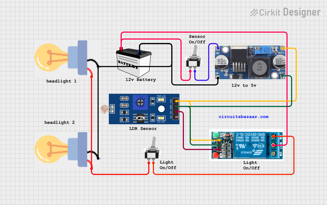
LDR-Activated Relay Control for Dual Bulb Illumination

Circuit Documentation
Summary of the Circuit
The circuit described by the provided inputs is a control system that utilizes a 5V relay to switch a load, which in this case appears to be a bulb. The relay is controlled by an LDR (Light Dependent Resistor) and a toggle switch. The power for the relay's coil and the LDR is provided by a 48V to 5V converter, which in turn is powered by a 12V battery. The circuit includes two bulbs that are powered directly by the 12V battery through a toggle switch. The LDR's digital output is connected to the relay's input, suggesting that the LDR may be used to trigger the relay based on light intensity.
Component List
5V Relay
- Pins: Normally Open, Common terminal, Normally Closed, In, GND, VCC
- Description: A relay is an electrically operated switch that allows you to control a high-power circuit with a low-power signal.
LDR (Light Dependent Resistor)
- Pins: A0, D0, GND, VCC
- Description: An LDR changes its resistance based on the ambient light level, typically used in light sensing applications.
48V to 5V Converter
- Pins: out+, out--, in+, in--
- Description: This component steps down the voltage from 48V to 5V to power low-voltage electronics.
Bulb
- Pins: GND, power
- Description: An electrical device that emits light when a current passes through it.
12V Battery (Small Size)
- Pins: VCC, GND
- Description: Provides the power source for the circuit.
Toggle Switch SPST (Single Pole Single Throw)
- Pins: L1, COM
- Description: A switch that can connect or disconnect the circuit at one contact point.
Wiring Details
5V Relay
- Common terminal: Connected to the VCC of the 12V Battery through a Toggle Switch SPST.
- Normally Closed: Connected to the COM of another Toggle Switch SPST.
- In: Connected to the D0 of the LDR.
- GND: Connected to the out-- of the 48V to 5V Converter.
- VCC: Connected to the out+ of the 48V to 5V Converter.
LDR (Light Dependent Resistor)
- D0: Connected to the In of the 5V Relay.
- GND: Connected to the out-- of the 48V to 5V Converter.
- VCC: Connected to the out+ of the 48V to 5V Converter.
48V to 5V Converter
- out+: Connected to the VCC of the LDR and the VCC of the 5V Relay.
- out--: Connected to the GND of the LDR and the GND of the 5V Relay.
- in+: Connected to the L1 of a Toggle Switch SPST.
- in--: Connected to the GND of the 12V Battery and the GND of both Bulbs.
Bulb
- GND: Connected to the GND of the 12V Battery.
- power: Connected to the L1 of a Toggle Switch SPST.
12V Battery (Small Size)
- VCC: Connected to the L1 of a Toggle Switch SPST.
- GND: Connected to the in-- of the 48V to 5V Converter and the GND of both Bulbs.
Toggle Switch SPST
- L1: One switch is connected between the VCC of the 12V Battery and the Common terminal of the 5V Relay, and the other is connected to the power of both Bulbs.
- COM: One switch is connected to the Normally Closed of the 5V Relay, and the other is connected to the in+ of the 48V to 5V Converter.
Documented Code
There is no code provided for any microcontrollers in the circuit. If the circuit is intended to include programmable logic or control, the relevant code would be documented in this section.