Cirkit Designer
Your all-in-one circuit design IDE
Home /
Project Documentation
Arduino Nano Controlled Smart Relay with APDS-9960 Gesture Sensor

Circuit Documentation
Summary of the Circuit
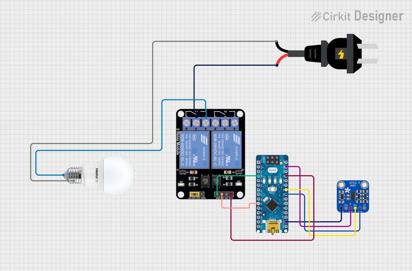
This circuit integrates an Arduino Nano microcontroller with an Adafruit APDS-9960 sensor and a 2-channel relay module to control an AC-powered bulb. The Arduino Nano serves as the central processing unit, interfacing with the APDS-9960 sensor via I2C communication and controlling the relay module to switch the bulb on or off. The AC source is connected to the relay module, which switches the bulb's power circuit.
Component List
Arduino Nano
- Description: A compact microcontroller board based on the ATmega328P.
- Purpose: Acts as the central controller for the circuit, interfacing with sensors and controlling the relay module.
- Pins: D1/TX, D0/RX, RESET, GND, D2, D3, D4, D5, D6, D7, D8, D9, D10, D11/MOSI, D12/MISO, VIN, 5V, A7, A6, A5, A4, A3, A2, A1, A0, AREF, 3V3, D13/SCK
Adafruit APDS-9960
- Description: A digital proximity, ambient light, RGB, and gesture sensor.
- Purpose: Provides input to the Arduino Nano for environmental sensing.
- Pins: VIN, 3.3V, GND, SCL, SDA, INT
Relay Module 2 Channel
- Description: A module with two independent relay switches.
- Purpose: Controls the AC power to the bulb based on signals from the Arduino Nano.
- Pins: GND, IN1, IN2, VCC, NC1, COM, NO1, NC2, NO2
AC Source
- Description: Provides alternating current power.
- Purpose: Supplies power to the bulb through the relay module.
- Pins: -, +
Bulb
- Description: An electrical device that emits light when powered by an AC source.
- Purpose: The load in the circuit, turned on or off by the relay module.
- Pins: +, -
Wiring Details
Arduino Nano
- GND connected to Relay Module GND and Adafruit APDS-9960 GND
- D7 connected to Relay Module IN1
- 5V connected to Relay Module VCC
- A5 (SCL) connected to Adafruit APDS-9960 SCL
- A4 (SDA) connected to Adafruit APDS-9960 SDA
- 3V3 connected to Adafruit APDS-9960 VIN
Adafruit APDS-9960
- VIN connected to Arduino Nano 3V3
- GND connected to Arduino Nano GND
- SCL connected to Arduino Nano A5
- SDA connected to Arduino Nano A4
Relay Module 2 Channel
- GND connected to Arduino Nano GND
- IN1 connected to Arduino Nano D7
- VCC connected to Arduino Nano 5V
- COM connected to AC Source -
- NO1 connected to Bulb +
AC Source
- connected to Relay Module COM
- connected to Bulb -
Bulb
- connected to Relay Module NO1
- connected to AC Source +
Documented Code
Arduino Nano Code (sketch.ino)
void setup() {
  // put your setup code here, to run once:

}

void loop() {
  // put your main code here, to run repeatedly:

}
Additional Notes (documentation.txt)
No additional code documentation provided.