Arduino-Controlled NRF24L01 Wireless DC Motor Driver System
Circuit Documentation
Summary
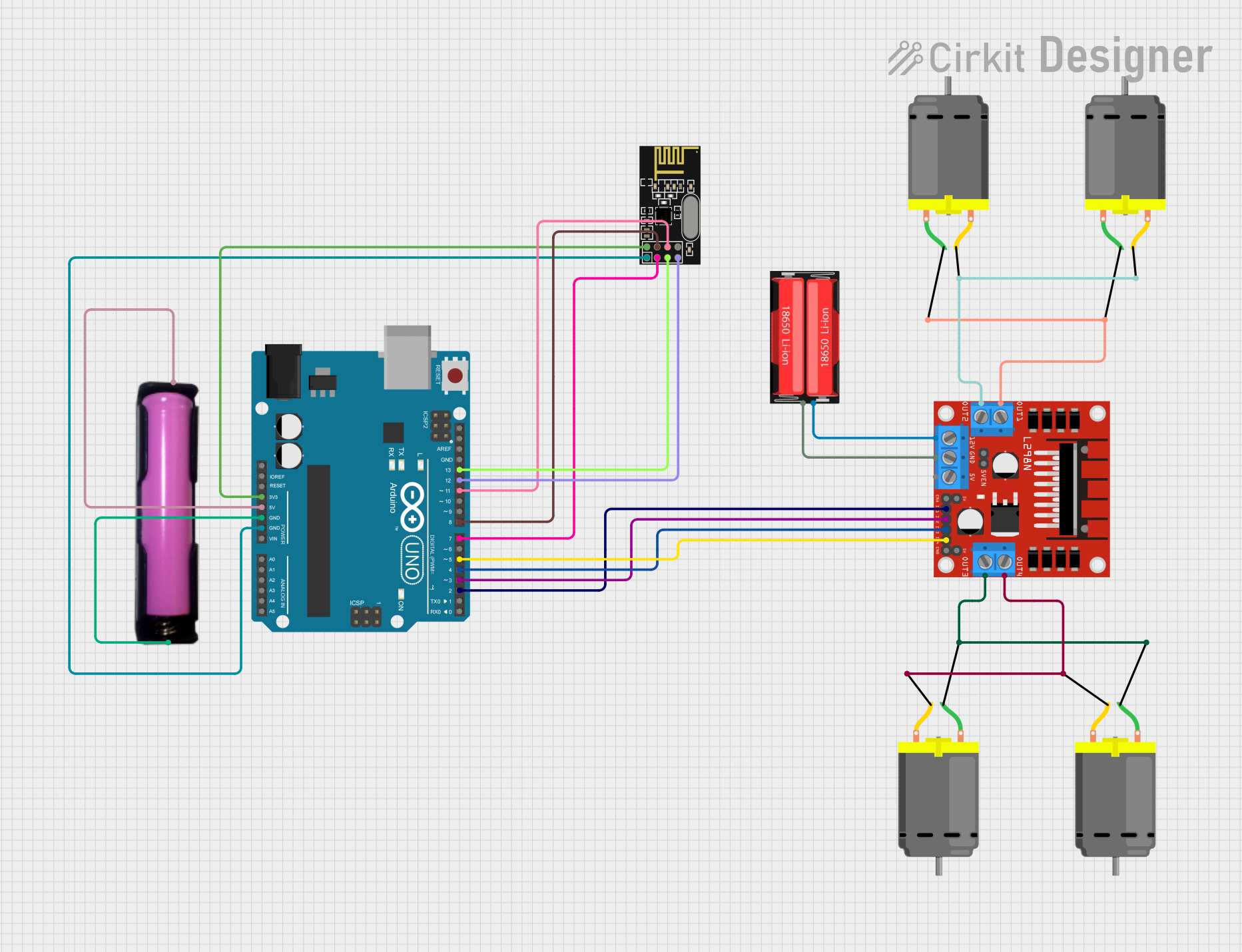
This circuit is designed to control a set of DC motors using an Arduino UNO microcontroller and an L298N DC motor driver. It also includes an NRF24L01 module for wireless communication. The power supply for the motor driver is provided by a 18650 Li-Ion battery, and the Arduino UNO is powered by a separate 18650 battery holder. The circuit is intended for applications where remote control of motors is required, such as robotics or automated systems.
Component List
Arduino UNO
- Microcontroller board based on the ATmega328P
- It has 14 digital input/output pins, 6 analog inputs, a 16 MHz quartz crystal, a USB connection, a power jack, an ICSP header, and a reset button.
L298N DC Motor Driver
- A module capable of driving two DC motors or one stepper motor.
- It has an onboard 5V regulator which can be enabled using a jumper.
NRF24L01
- A 2.4GHz wireless transceiver module.
- It has configurable data rates and low power consumption modes.
18650 Li-Ion Battery
- A rechargeable battery providing a nominal voltage typically around 3.7V.
DC Motor
- A simple electric motor that runs on direct current (DC) power.
18650 Battery Holder
- A holder for an 18650 Li-Ion battery, providing easy connection points for VCC and GND.
Wiring Details
Arduino UNO
3.3Vconnected to NRF24L01 VCC (3V)5Vconnected to 18650 battery holder VCCGNDconnected to 18650 battery holder GND and NRF24L01 GNDD13connected to NRF24L01 SCKD12connected to NRF24L01 MISOD11connected to NRF24L01 MOSID8connected to NRF24L01 CSND7connected to NRF24L01 CED5connected to L298N DC motor driver IN4D4connected to L298N DC motor driver IN3D3connected to L298N DC motor driver IN2D2connected to L298N DC motor driver IN1
L298N DC Motor Driver
OUT1connected to two DC Motors (pin 1)OUT2connected to the same two DC Motors (pin 2)OUT3connected to another two DC Motors (pin 1)OUT4connected to the same two DC Motors (pin 2)12Vconnected to 18650 Li-Ion battery PositiveGNDconnected to 18650 Li-Ion battery Negative
NRF24L01
VCC (3V)connected to Arduino UNO 3.3VGNDconnected to Arduino UNO GNDCEconnected to Arduino UNO D7CSNconnected to Arduino UNO D8SCKconnected to Arduino UNO D13MISOconnected to Arduino UNO D12MOSIconnected to Arduino UNO D11
18650 Li-Ion Battery
Positiveconnected to L298N DC motor driver 12VNegativeconnected to L298N DC motor driver GND
DC Motor
- Four DC Motors connected to L298N DC motor driver OUT1, OUT2, OUT3, and OUT4 respectively.
18650 Battery Holder
VCCconnected to Arduino UNO 5VGNDconnected to Arduino UNO GND
Documented Code
Arduino UNO Code (sketch.ino)
void setup() {
  // put your setup code here, to run once:

}

void loop() {
  // put your main code here, to run repeatedly:

}
The provided code is a template with empty setup and loop functions. The setup function is intended to initialize settings, while the loop function will contain the main logic that the Arduino will execute repeatedly. Specific functionality needs to be implemented based on the requirements of the application.