
Circuit Documentation
Summary of the Circuit
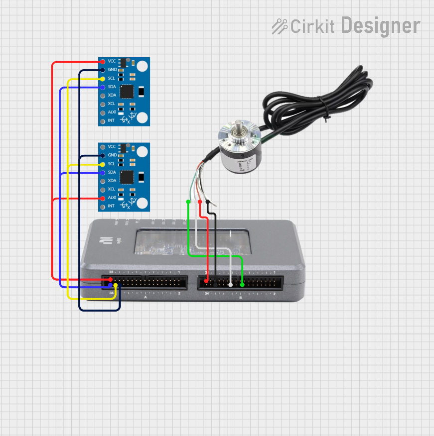
This circuit integrates two MPU6050 sensors with a myRIO controller and an encoder. The MPU6050 sensors are used for motion tracking, as they are 6-axis motion tracking devices that combine a 3-axis gyroscope and a 3-axis accelerometer. The myRIO controller, likely a National Instruments device, is used for data acquisition and control purposes. The encoder is used to measure the position, velocity, and direction of a rotating shaft or object.
Component List
MPU6050
- Description: A 6-axis motion tracking device that combines a 3-axis gyroscope and a 3-axis accelerometer.
- Pins: vcc, gnd, scl, sda, xda, xcl, AD0, int, 3.3v
myRIO
- Description: A reconfigurable I/O (RIO) device from National Instruments designed for data acquisition and control.
- Pins: VCC, SDA, SCL, GND, Phase A, Phase B
Encoder
- Description: A device that converts the angular position or motion of a shaft or axle to an analog or digital signal.
- Pins: Phase A, VCC, Phase B, GND
Wiring Details
MPU6050
- VCC: Connected to myRIO VCC.
- GND: Connected to myRIO GND.
- SCL: Connected to myRIO SCL.
- SDA: Connected to myRIO SDA.
- Other Pins: Not connected in this circuit.
myRIO
- VCC: Connected to MPU6050 VCC and Encoder VCC.
- GND: Connected to MPU6050 GND and Encoder GND.
- SCL: Connected to MPU6050 SCL.
- SDA: Connected to MPU6050 SDA.
- Phase A: Connected to Encoder Phase B.
- Phase B: Connected to Encoder Phase A.
Encoder
- VCC: Connected to myRIO VCC.
- GND: Connected to myRIO GND.
- Phase A: Connected to myRIO Phase B.
- Phase B: Connected to myRIO Phase A.
Documented Code
No code has been provided for the microcontrollers in the circuit. If code becomes available, it should be documented in this section with appropriate comments and explanations for each function and routine.