
Arduino Mega 2560-Based Modular Control System with I2C LCD and Peripheral Interfaces
View and Edit Project In Cirkit Designer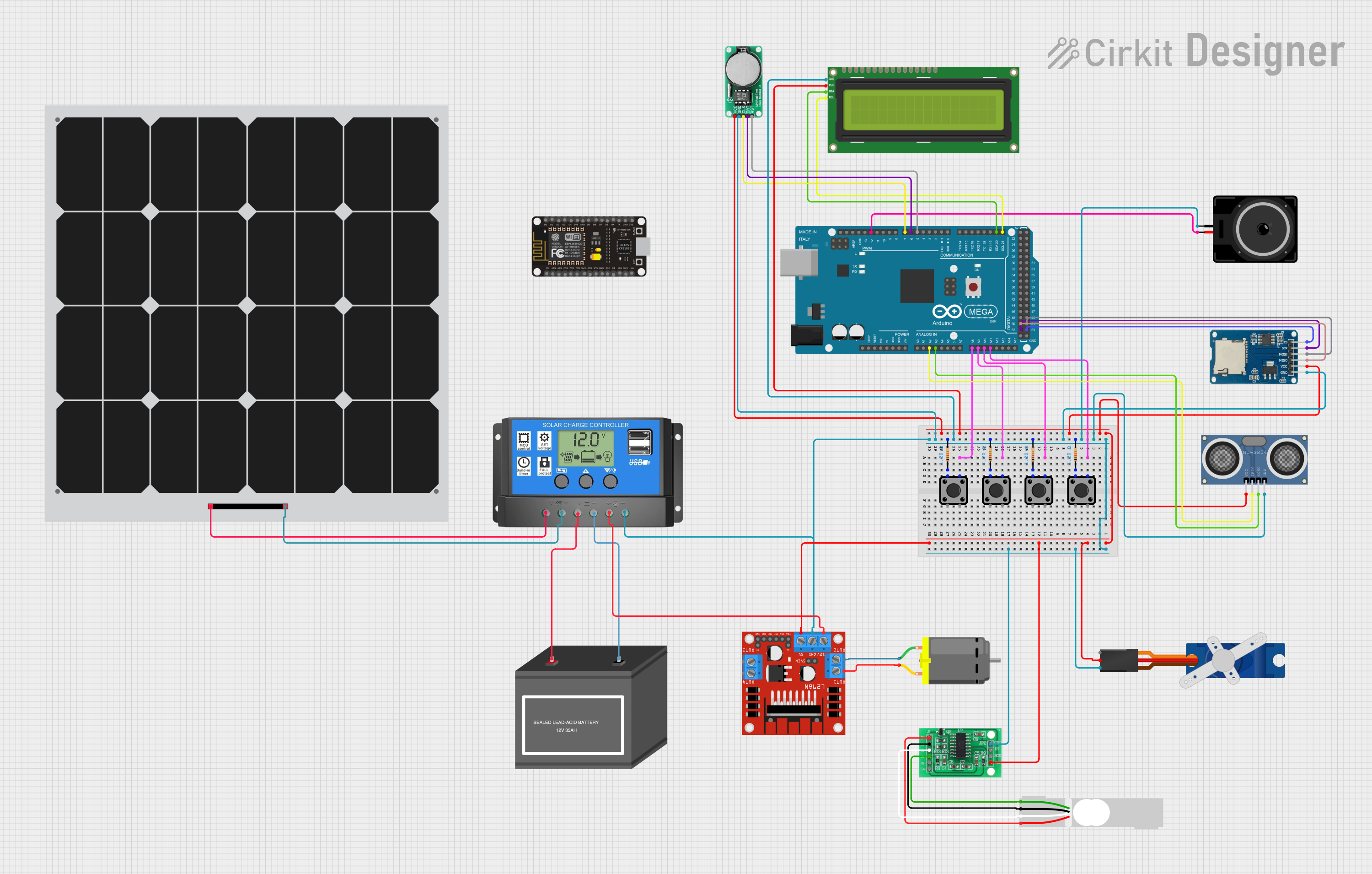
Circuit Documentation
Summary
This document provides a detailed overview of a circuit designed to interface various components with an Arduino Mega 2560 microcontroller. The circuit includes input devices (tactile switches), output devices (LCD screen, DC motor, servo, loudspeaker), sensors (ultrasonic distance sensor, load cell), a motor driver, a real-time clock, a micro SD card module, and power management components (solar panel, battery, solar charge controller). The circuit is designed to perform multiple functions, which could include user input handling, data display, motor control, data logging, timekeeping, and distance measurement.
Component List
Microcontroller
- Arduino Mega 2560: A microcontroller board based on the ATmega2560, with numerous digital and analog I/O pins.
Input Devices
- Tactile Switch Buttons - 12mm Square: Pushbutton switches used for user input.
Output Devices
- I2C LCD 16x2 Screen: A 16x2 character LCD display that uses the I2C communication protocol.
- DC Motor: An electric motor that converts electrical energy into mechanical motion.
- Tower Pro SG90 servo: A small and lightweight servo motor for precise control.
- Loudspeaker: An electroacoustic transducer used to produce sound.
Sensors
- HC-SR04 Ultrasonic Distance Sensor: A sensor that measures distance by emitting ultrasonic waves and measuring the time taken for the echo to return.
- Load Cell - Red/white/black/green: A transducer that converts force into an electrical signal.
- HX711 - Bridge Sensor Interface: An ADC converter designed for weighing scales and industrial control applications to interface directly with a bridge sensor.
Motor Driver
- L298N DC motor driver: A high-power motor driver capable of driving DC motors.
Power Management
- Solar Panel: A panel designed to absorb the sun's rays as a source of energy for generating electricity.
- 12V Battery (mini): A small 12V battery used to store electrical energy.
- Solar Charge Controller: A device that controls the charging of a battery from a solar panel and protects the battery from overcharging.
Timekeeping
- DS1302 RTC: A real-time clock module for keeping track of the current time and date.
Data Storage
- Micro SD Card Module: A module that allows an Arduino to read and write data to a micro SD card.
Communication Module
- esp8266 nodemcu: A Wi-Fi module that allows microcontrollers to connect to a Wi-Fi network.
Passive Components
- Resistor: A passive two-terminal electrical component that implements electrical resistance as a circuit element.
Wiring Details
Arduino Mega 2560
- A11: Connected to Tactile Switch Button
- A10: Connected to Tactile Switch Button
- A9: Connected to Tactile Switch Button
- A8: Connected to Tactile Switch Button
- A2: Connected to HC-SR04 Ultrasonic Distance Sensor (TRIG)
- A3: Connected to HC-SR04 Ultrasonic Distance Sensor (ECHO)
- D21/SCL: Connected to I2C LCD 16x2 Screen (SCL)
- D20/SDA: Connected to I2C LCD 16x2 Screen (SDA)
- D5 PWM: Connected to DS1302 RTC (RST)
- D6 PWM: Connected to DS1302 RTC (DATA)
- D7 PWM: Connected to DS1302 RTC (CLK)
- D12 PWM: Connected to Loudspeaker
- D52: Connected to Micro SD Card Module (sck)
- D50: Connected to Micro SD Card Module (miso)
- D53: Connected to Micro SD Card Module (cs)
- D51: Connected to Micro SD Card Module (mosi)
Tactile Switch Buttons - 12mm Square
- Pin 3: Connected to Arduino Mega 2560 (A11, A10, A9, A8)
- Pin 4: Connected to Resistor (pin1)
I2C LCD 16x2 Screen
- SCL: Connected to Arduino Mega 2560 (D21/SCL)
- SDA: Connected to Arduino Mega 2560 (D20/SDA)
- VCC (5V): Connected to power supply net
- GND: Connected to ground net
DC Motor
- Pin 1: Connected to L298N DC motor driver (OUT2)
- Pin 2: Connected to L298N DC motor driver (OUT1)
Tower Pro SG90 servo
- Signal: Not specified in net list
- +5V: Connected to power supply net
- GND: Connected to ground net
Loudspeaker
- Pin 1: Connected to ground net
- Pin 2: Connected to Arduino Mega 2560 (D12 PWM)
HC-SR04 Ultrasonic Distance Sensor
- VCC: Connected to power supply net
- TRIG: Connected to Arduino Mega 2560 (A2)
- ECHO: Connected to Arduino Mega 2560 (A3)
- GND: Connected to ground net
Load Cell - Red/white/black/green
- E+: Connected to HX711 (E+)
- A-: Connected to HX711 (A-)
- E-: Connected to HX711 (E-)
- A+: Connected to HX711 (A+)
L298N DC motor driver
- OUT1, OUT2: Connected to DC Motor
- 12V: Connected to Solar Charge Controller (Load +)
- GND: Connected to ground net
- 5V: Connected to power supply net
Solar Panel
- +: Connected to Solar Charge Controller (Solar Cell +)
- -: Connected to Solar Charge Controller (Solar Cell -)
12V Battery (mini)
- +: Connected to Solar Charge Controller (Battery +)
- -: Connected to Solar Charge Controller (Battery -)
Solar Charge Controller
- Solar Cell +: Connected to Solar Panel (+)
- Solar Cell -: Connected to Solar Panel (-)
- Battery +: Connected to 12V Battery (mini) (+)
- Battery -: Connected to 12V Battery (mini) (-)
- Load +: Connected to L298N DC motor driver (12V)
- Load -: Connected to ground net
HX711 - Bridge Sensor Interface
- E+, E-, A-, A+: Connected to Load Cell
- GND - GROUND: Connected to ground net
- DATA (OUT): Not specified in net list
- SCK - CLOCK (IN): Not specified in net list
- 3.3/3.5V Supply: Connected to power supply net
DS1302 RTC
- VCC: Connected to power supply net
- GND: Connected to ground net
- CLK: Connected to Arduino Mega 2560 (D7 PWM)
- DATA: Connected to Arduino Mega 2560 (D6 PWM)
- RST: Connected to Arduino Mega 2560 (D5 PWM)
Micro SD Card Module
- cs: Connected to Arduino Mega 2560 (D53)
- sck: Connected to Arduino Mega 2560 (D52)
- mosi: Connected to Arduino Mega 2560 (D51)
- miso: Connected to Arduino Mega 2560 (D50)
- vcc: Connected to power supply net
- gnd: Connected to ground net
Resistor
- Pin 1: Connected to Tactile Switch Button (Pin 4)
- Pin 2: Connected to ground net
Documented Code
Arduino Mega 2560 Code (sketch.ino)
void setup() {
  // put your setup code here, to run once:

}

void loop() {
  // put your main code here, to run repeatedly:

}
Note: The provided code is a template and does not include specific functionality. It needs to be completed with the logic required for the circuit's intended operation.