Cirkit Designer
Your all-in-one circuit design IDE
Home /
Project Documentation
ESP32-Based Smart Temperature-Controlled Fan System with Wi-Fi Connectivity

Circuit Documentation
Summary
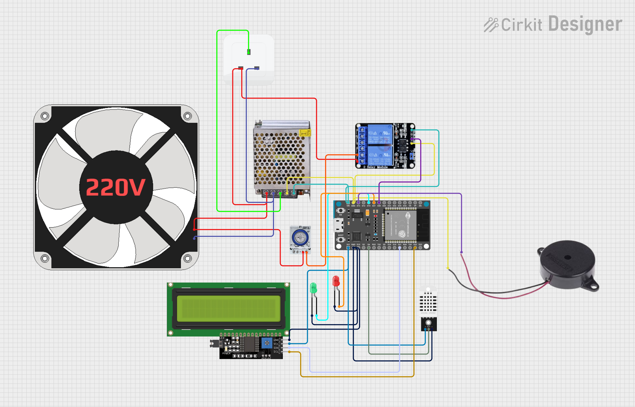
The circuit is designed to control a 220V fan and monitor temperature and humidity using an ESP32 Devkit V1 microcontroller. The system includes a DHT22 sensor for measuring temperature and humidity, a two-channel 5V relay to control the fan, LEDs for status indication, an LCD display for user feedback, a buzzer for alerts, and a power supply to provide the necessary voltages. The ESP32 is programmed to communicate with the Blynk platform for remote monitoring and control.
Component List
ESP32 Devkit V1
- Microcontroller with WiFi capability.
- It has multiple digital I/O pins and supports I2C communication.
Two Channel Relay 5v
- A relay module with two channels that can control high voltage/high current devices.
220V Fan
- A standard fan operating at 220V for air circulation.
LED: Two Pin (red)
- A red LED used for status indication.
LED: Two Pin (green)
- A green LED used for status indication.
DHT22
- A sensor for measuring temperature and humidity.
LCD Display 16x4 I2C
- An LCD display with I2C interface for showing information to the user.
POWER SUPPLY 5V 5AMP
- A power supply unit that provides 5V DC and supports up to 5A current.
Buzzer
- An audible alert device.
Socket
- An AC power socket for connecting the fan and power supply.
Timer
- A timer module for scheduling operations.
Wiring Details
ESP32 Devkit V1
3V3connected to DHT22 VCC and LCD Display VCC.GNDconnected to DHT22 GND, LCD Display GND, both LED cathodes, Buzzer NEGATIVE, and Two Channel Relay GND.D4connected to DHT22 OUT.D21(SDA) andD22(SCL) connected to LCD Display I2C pins.D26connected to Two Channel Relay IN1.D27connected to Red LED anode.D14connected to Green LED anode.D13connected to Buzzer POSITIVE.VINconnected to Two Channel Relay VCC and POWER SUPPLY 12V-24V Output (DC).
Two Channel Relay 5v
IN1andIN2controlled by ESP32.VCCconnected to ESP32 VIN.GNDconnected to ESP32 GND.C1connected to Timer L1.NO1connected to 220V Fan L, Timer L2, Socket life, and POWER SUPPLY 220V Positive Pole (AC).
220V Fan
Nconnected to Socket neutral and POWER SUPPLY 220V Negative Pole (AC).Lconnected to Relay NO1.
LED: Two Pin (red)
cathodeconnected to ESP32 GND.anodeconnected to ESP32 D27.
LED: Two Pin (green)
cathodeconnected to ESP32 GND.anodeconnected to ESP32 D14.
DHT22
VCCconnected to ESP32 3V3.OUTconnected to ESP32 D4.GNDconnected to ESP32 GND.
LCD Display 16x4 I2C
SCLconnected to ESP32 D22.SDAconnected to ESP32 D21.VCCconnected to ESP32 3V3.GNDconnected to ESP32 GND.
POWER SUPPLY 5V 5AMP
220V Positive Pole (AC)connected to Relay NO1.220V Negative Pole (AC)connected to 220V Fan N.GND (DC)connected to ESP32 GND.12V-24V Output (DC)connected to ESP32 VIN.
Buzzer
POSITIVEconnected to ESP32 D13.NEGATIVEconnected to ESP32 GND.
Socket
earthconnected to POWER SUPPLY GND.lifeconnected to Relay NO1.neutralconnected to 220V Fan N.
Timer
S1andS2not connected.L1connected to Relay C1.L2connected to Relay NO1.
Documented Code
ESP32 Devkit V1 Code
#define BLYNK_TEMPLATE_ID "TMPL6-vn2VN_V"
#define BLYNK_TEMPLATE_NAME "Quickstart Template"
#define BLYNK_AUTH_TOKEN "vO02bgbn-43wyzsgJdoY47qDX3Jl8R8y"

/* Comment this out to disable prints and save space */
#define BLYNK_PRINT Serial

#include <DHT.h>
#include <WiFi.h>
#include <BlynkSimpleEsp32.h>
#include <Wire.h>
#include <LiquidCrystal_I2C.h>  // I2C LCD library

#define DHTPIN 4                 // Pin where the DHT22 data pin is connected
#define DHTTYPE DHT22            // DHT 22 (AM2302)
#define RELAY_PIN 26             // GPIO pin where relay is connected (IN1)
#define RED_LED_PIN 27           // GPIO pin where RED LED is connected
#define GREEN_LED_PIN 14         // GPIO pin where GREEN LED is connected
#define TEMP_MAX_THRESHOLD 65.0  // Maximum temperature threshold in Celsius
#define TEMP_MIN_THRESHOLD 60.0  // Minimum temperature threshold in Celsius

// WiFi credentials
char ssid[] = "haiyaaa";
char pass[] = "430578440";

// Initialize DHT sensor
DHT dht(DHTPIN, DHTTYPE);

// Initialize I2C LCD (address 0x27)
LiquidCrystal_I2C lcd(0x27, 16, 2);

bool blowerState = false;  // Blower state, controlled by Blynk
int blowerbutton;
int countdown = 0;  // Timer countdown (initially 0 seconds)
bool countdownActive = false;
BlynkTimer timer;  // Timer for sensor values and countdown

void setup() {
  Serial.begin(115200);
  dht.begin();  // Start reading the DHT sensor

  // Set relay and LED pins as outputs
  pinMode(RELAY_PIN, OUTPUT);
  pinMode(RED_LED_PIN, OUTPUT);
  pinMode(GREEN_LED_PIN, OUTPUT);

  // Ensure relay and RED LED are off initially, GREEN LED is off
  digitalWrite(RELAY_PIN, HIGH);      // Turn off the relay initially
  digitalWrite(RED_LED_PIN, LOW);     // Turn RED LED off initially
  digitalWrite(GREEN_LED_PIN, LOW);   // Turn GREEN LED off initially

  Serial.println("System initialized...");

  // Initialize LCD
  lcd.init();           // Initialize the LCD with 16 columns and 2 rows
  lcd.backlight();      // Turn on the LCD backlight
  lcd.setCursor(0, 0);
  lcd.print("Connecting to");
  lcd.setCursor(0, 1);
  lcd.print("Wifi");

  // Initialize Blynk connection
  Blynk.begin(BLYNK_AUTH_TOKEN, ssid, pass);
  lcd.clear();
  lcd.setCursor(0, 0);
  lcd.print("Connected!!");

  delay(3000);

  lcd.clear();
  lcd.setCursor(0, 0);
  lcd.print("Cloth Dryer");

  digitalWrite(RELAY_PIN, HIGH);      // Turn blower OFF
  digitalWrite(RED_LED_PIN, LOW);     // Turn RED LED OFF (blower is OFF)
  digitalWrite(GREEN_LED_PIN, LOW);   // Turn GREEN LED OFF

  // Set a timer to read the sensor values every 2 seconds
  timer.setInterval(2000L, readDHTAndSendToBlynk);
}

// Blynk virtual pin to control the blower (relay)
BLYNK_WRITE(V1) {
  blowerbutton = param.asInt();  // Get value from Blynk app (1 or 0)

  if (blowerbutton == 1 && !countdownActive) {
    // If the blower is manually turned on from Blynk, start countdown
    countdownActive = true;
    startBlower();
  } else if (blowerbutton == 0) {
    stopBlower();  // Stop the blower if turned off in Blynk
  }
}

// Function to set the timer duration via Blynk app
BLYNK_WRITE(V2) {
  int timeSelected = param.asInt();  // Get selected time in minutes
  countdown = timeSelected * 60;  // Convert minutes to seconds
  if (countdown > 0) {
    countdownActive = true;
    startBlower();
    timer.setInterval(1000L, countdownFunction);  // Start countdown every second
  }
}

// Function to start the blower
void startBlower() {
  digitalWrite(RELAY_PIN, LOW);     // Turn blower ON
  digitalWrite(RED_LED_PIN, HIGH);  // Turn RED LED ON
  digitalWrite(GREEN_LED_PIN,