
ESP8266 NodeMCU with LoRa and RS-485 Communication Interface
View and Edit Project In Cirkit Designer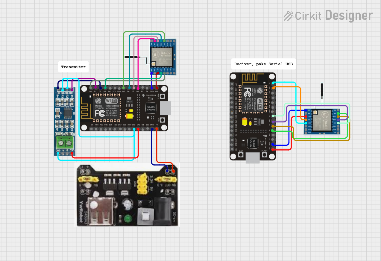
Circuit Documentation
Summary
The circuit in question is designed to interface an ESP8266 NodeMCU microcontroller with two LoRa Ra-02 SX1278 modules and an RS-485 module. The ESP8266 NodeMCU is responsible for controlling the LoRa modules for wireless communication and the RS-485 module for wired communication. The MB102 Breadboard Power Supply Module provides power to the ESP8266 NodeMCU. The circuit is likely intended for applications that require both long-range wireless and reliable wired communication capabilities.
Component List
ESP8266 NodeMCU
- Description: A WiFi-enabled microcontroller module that is based on the ESP8266 SoC.
- Pins: D0-D8, RX, TX, A0, RSV, SD3, SD2, SD1, CMD, SD0, CLK, EN, RST, VIN, 3V3, GND
LoRa Ra-02 SX1278
- Description: A wireless communication module that uses the LoRa technology for long-range communication.
- Pins: GND, NSS, MOSI, MISO, SCK, D105, DI04, 3.3V, RST, DI00, DI01, D102, DI03
RS-485 Module
- Description: A module for wired communication using the RS-485 standard.
- Pins: VCC, B, A, GND, RO, RE, DE, DI
MB102 Breadboard Power Supply Module 3.3V/5V
- Description: A power supply module that can provide 3.3V or 5V to a breadboard.
- Pins: GND, 3.3V, 5V
Wiring Details
ESP8266 NodeMCU
- D0: Connected to DI00 on LoRa Ra-02 SX1278
- D1: Connected to RO on RS-485 Module
- D2: Connected to DI on RS-485 Module
- D3: Connected to RST on LoRa Ra-02 SX1278
- D5: Connected to SCK on LoRa Ra-02 SX1278
- D6: Connected to MISO on LoRa Ra-02 SX1278
- D7: Connected to MOSI on LoRa Ra-02 SX1278
- D8: Connected to NSS on LoRa Ra-02 SX1278
- GND: Connected to GND on LoRa Ra-02 SX1278, RS-485 Module, and MB102 Breadboard Power Supply Module
- 3V3: Connected to 3.3V on LoRa Ra-02 SX1278 and VCC on RS-485 Module
- VIN: Connected to 5V on MB102 Breadboard Power Supply Module
LoRa Ra-02 SX1278
- NSS: Connected to D8 on ESP8266 NodeMCU
- MOSI: Connected to D7 on ESP8266 NodeMCU
- MISO: Connected to D6 on ESP8266 NodeMCU
- SCK: Connected to D5 on ESP8266 NodeMCU
- GND: Connected to GND on ESP8266 NodeMCU
- 3.3V: Connected to 3V3 on ESP8266 NodeMCU
- RST: Connected to D3 on ESP8266 NodeMCU
- DI00: Connected to D0 on ESP8266 NodeMCU
RS-485 Module
- RO: Connected to D1 on ESP8266 NodeMCU
- DI: Connected to D2 on ESP8266 NodeMCU
- GND: Connected to GND on ESP8266 NodeMCU
- RE/DE: Connected to GND on ESP8266 NodeMCU (assuming RE and DE are tied together for automatic transmit/receive control)
- VCC: Connected to 3V3 on ESP8266 NodeMCU
MB102 Breadboard Power Supply Module 3.3V/5V
- GND: Connected to GND on ESP8266 NodeMCU
- 5V: Connected to VIN on ESP8266 NodeMCU
Documented Code
No code has been provided for the microcontrollers in the circuit. The documentation of the code would typically include descriptions of the functionality implemented, setup and loop functions, and any libraries used for interfacing with the LoRa and RS-485 modules. Since no code is available, this section cannot be completed.