Cirkit Designer
Your all-in-one circuit design IDE
Home /
Project Documentation
Arduino Mega 2560 Controlled Interactive Sound and Light System
Circuit Documentation
Summary
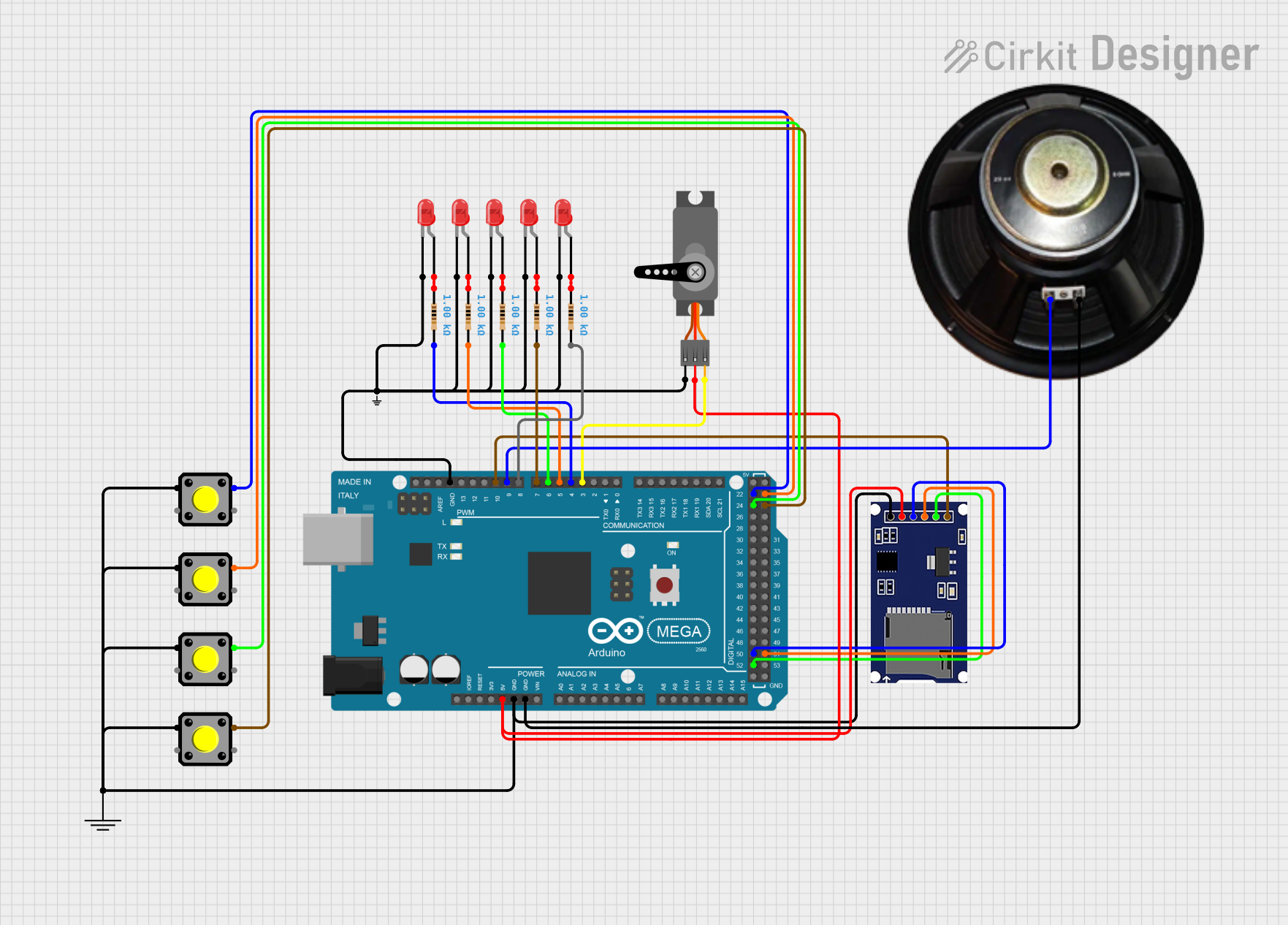
This circuit is designed to control a series of LEDs, a servo motor, a speaker, and read inputs from pushbuttons using an Arduino Mega 2560 microcontroller. The circuit includes multiple red two-pin LEDs, each with a corresponding resistor to limit current. Pushbuttons are used to trigger different actions, such as playing audio files from an SD card, moving a servo motor, and changing LED patterns. The speaker is controlled by the microcontroller to play audio, and the SD card module is used for audio file storage. The ground connections are common for all components, and the servo and SD module receive power from the Arduino's 5V output.
Component List
LEDs
- LED: Two Pin (red): A red light-emitting diode with an anode and cathode pin.
Resistors
- Resistor: A passive component with two pins, providing 1000 Ohms of resistance to limit current to the LEDs.
Pushbuttons
- Pushbutton: A momentary switch with four pins, used to trigger different actions in the circuit.
Microcontroller
- Arduino Mega 2560: A microcontroller board based on the ATmega2560, with a variety of digital and analog I/O pins.
Ground and Power
- GND: A ground reference point for the circuit.
- Small GND: An additional ground reference point.
- Servo: An actuator with three pins: ground (GND), power (VCC), and control (PWM).
- SDmodule: A module for reading and writing to SD cards, with pins for chip select (CS), serial clock (SCK), master out slave in (MOSI), master in slave out (MISO), power (VCC), and ground (GND).
- Speaker: An audio output device with a positive (+) and negative (-) terminal.
Wiring Details
LEDs
- LEDs: Each LED's cathode is connected to the ground, and the anode is connected to a resistor. The other end of the resistor is connected to a designated PWM pin on the Arduino for individual control.
Resistors
- Resistors: Each resistor is connected in series with an LED to limit the current. The other end of each resistor is connected to a PWM pin on the Arduino.
Pushbuttons
- Pushbuttons: One side of each pushbutton is connected to the ground, and the other side is connected to a digital input pin on the Arduino. The internal pull-up resistors are enabled in the code.
Servo
- Servo: The servo's ground and power pins are connected to the Arduino's ground and 5V pins, respectively. The control pin is connected to a PWM pin on the Arduino.
SDmodule
- SDmodule: The module's ground and power pins are connected to the Arduino's ground and 5V pins, respectively. The CS, SCK, MOSI, and MISO pins are connected to the corresponding SPI pins on the Arduino.
Speaker
- Speaker: The speaker's negative terminal is connected to the ground, and the positive terminal is connected to a PWM pin on the Arduino.
Documented Code
// Libraries Used
#include <SD.h>
#include <TMRpcm.h>
#include <SPI.h>

// TMRpcm and SD Library Setups
TMRpcm audio;    // Create an object for the TMRpcm library
const int chipSelect = 10; // SD card module chip select pin

// Pre Setup Section
// PIN ASSIGNMENTS (Change the number to the corresponding pin you decide to use)
//  LED Pins (Only requires basic Digital Pins)
const int led1 = 4;
const int led2 = 5;
const int led3 = 6;
const int led4 = 7;
const int led5 = 8;
//  Button Pins. (Only Requires Basic Digital Pins)
const int button1 = 22;
const int button2 = 23;
const int button3 = 24;
const int button4 = 25;
//  Servo Pins (Requires PWM pins.)
const int servoPin = 3; // Must be a PWM pin.
//  Speaker Pins
const int speakerPin1 = 9;  // Set the pin for the speaker. Must be a PWM pin linked to Timer 1 on the board. (Most Arduino's this means pin 9 or 10)

// Global Variables
const int servoSpeed = 100; // Can be any value from 0-255. 0 is stopped 255 is full speed.
unsigned long currentMillis = 0;

// Audio File Names
char button1Audio[] = "button1audio.wav";  // Replace the text inside the quotes with the actual file names on the root directory of SD card.
char button2Audio[] = "button2audio.wav";  // Replace the text inside the quotes with the actual file names on the root directory of SD card.
char button3Audio[] = "button3audio.wav";  // Replace the text inside the quotes with the actual file names on the root directory of SD card.
char button4Audio[] = "button4audio.wav";  // Replace the text inside the quotes with the actual file names on the root directory of SD card.

// Button Press Millis Setup
const long button1Interval = 10000; // Set To length of WAV file for this button
const long button2Interval = 10000; // Set To length of WAV file for this button
const long button3Interval = 10000; // Set To length of WAV file for this button
const long button4Interval = 10000; // Set To length of WAV file for this button
unsigned long button1PrevMillis = 0;
unsigned long button2PrevMillis = 0;
unsigned long button3PrevMillis = 0;
unsigned long button4PrevMillis = 0;

// Button Active Variables
bool button1Active = false;
bool button2Active = false;
bool button3Active = false;
bool button4Active = false;
bool anyButtonActive = false;

// LED Millis Setup
int ledState = 0;
const long led1Interval = 500;
const long led2Interval = 500;
const long led3Interval = 500;
const long led4Interval = 500;
unsigned long ledPrevMillis = 0;

// Setup and initialize. This only runs once.
void setup()
{
  Serial.begin(9600);

  // Initializes the SD card and checks to make sure it was successful.
  if (!SD.begin(chipSelect))
  {
    Serial.println("SD card initialization failed.");
    return;
  }
  Serial.println("SD card ready.");

  // Setup Pin Modes
  //  Output Pins
  pinMode(led1, OUTPUT);
  pinMode(led2, OUTPUT);
  pinMode(led3, OUTPUT);
  pinMode(led4, OUTPUT);
  pinMode(led5, OUTPUT);
  pinMode(servoPin, OUTPUT);
  //  Input Pins
  pinMode(button1, INPUT_PULLUP); // Only use the _PULLUP part if you don't wire your own resistors in between the Button and 5V pin. (this goes for all buttons)
  pinMode(button2, INPUT_PULLUP);
  pinMode(button3, INPUT_PULLUP);
  pinMode(button4, INPUT_PULLUP);

  // Audio Output Setup
  audio.speakerPin = speakerPin1;
  audio.setVolume(6); // Set Volume (0-7)
  audio.quality(1); // Default Quality= 0, Higher Quality = 1
}

// This loop is what runs continuously over and over.
void loop()
{
  // Get Current Millis
  currentMillis = millis();

  // Check if any button is active
  if (button1Active || button2Active || button3Active || button4Active)
  {
    anyButtonActive = true;
  }
  else
  {
    anyButtonActive = false;
  }

  // Checks to see if timer has ran out on the Audio file (activeButton). If so, it stops everything.
  if (button1Active && currentMillis - button1PrevMillis >= button1Interval)
  {
    stopAllActions();
  }
  else if (button2Active && currentMillis - button2PrevMillis >= button2Interval)
  {
    stopAllActions();
  }
  else if (button3Active && currentMillis - button3PrevMillis >= button3Interval)
  {
    stopAllActions();
  }
  else if (button4Active && currentMillis - button4PrevMillis >= button4Interval)
  {
    stopAllActions();
  }

  // Starts the corresponding LED pattern depending on active button
  if (button1Active && currentMillis - ledPrevMillis >= led1Interval)
  {
    led1Sequence();
  }
  else if (button2Active && currentMillis - ledPrevMillis >= led2Interval)
  {
    led2Sequence();
  }
  else if (button3Active && currentMillis - ledPrevMillis >= led3Interval)
  {
    led3Sequence();
  }
  else if (button4Active && currentMillis - ledPrevMillis >= led4Interval)
  {
    led4Sequence();
  }

  // Check For Button Presses
  bool button1Press = !digitalRead(button1);
  bool button2Press = !digitalRead(button2);
  bool button3Press = !digitalRead(button3);
  bool button4Press = !digitalRead(button4);

  if (button1