Cirkit Designer
Your all-in-one circuit design IDE
Home /
Project Documentation
Arduino UNO Controlled Dimmable LED Light
Circuit Documentation
Summary
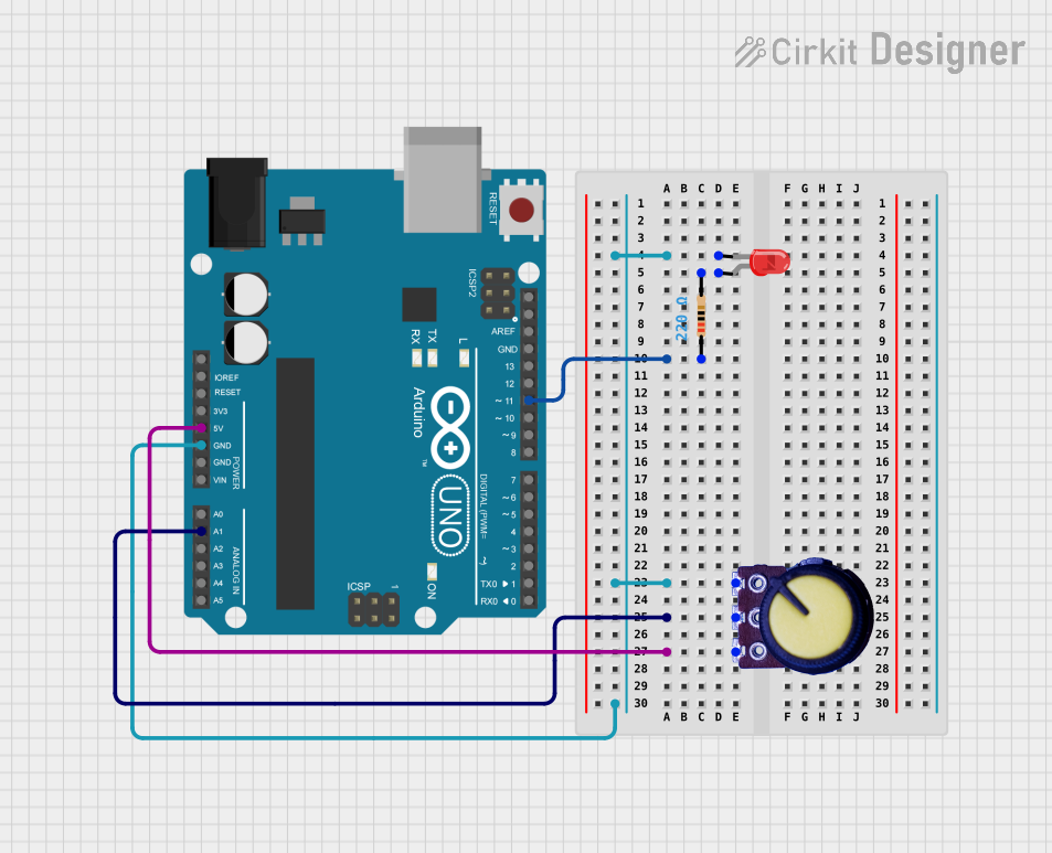
This circuit consists of an Arduino UNO microcontroller interfaced with a potentiometer and an LED with a series resistor. The potentiometer is used to provide an analog input to the Arduino, which can be used to control the brightness of the LED or other similar functions. The LED is connected to the Arduino through a 220-ohm resistor to limit the current and protect the LED from damage.
Component List
Potentiometer
- Pins: GND, Output, VCC
- Description: A variable resistor with three terminals. It is used to adjust the level of the voltage between VCC and GND.
Arduino UNO
- Pins: UNUSED, IOREF, Reset, 3.3V, 5V, GND, Vin, A0-A5, SCL, SDA, AREF, D0-D13
- Description: A microcontroller board based on the ATmega328P. It has digital input/output pins, analog inputs, a USB connection for programming, and power management features.
Resistor
- Pins: pin1, pin2
- Description: A passive two-terminal electrical component that implements electrical resistance as a circuit element.
- Properties: Resistance: 220 Ohms
LED: Two Pin (red)
- Pins: cathode, anode
- Description: A red light-emitting diode that emits light when a current flows through it in the forward direction.
Wiring Details
Potentiometer
- GND: Connected to Arduino UNO GND and LED cathode.
- Output: Connected to Arduino UNO Analog Pin A1.
- VCC: Connected to Arduino UNO 5V.
Arduino UNO
- GND: Connected to Potentiometer GND and LED cathode.
- 5V: Connected to Potentiometer VCC.
- A1: Connected to Potentiometer Output.
- D11: Connected to one end of the Resistor (pin1).
Resistor
- pin1: Connected to Arduino UNO Digital Pin D11.
- pin2: Connected to LED anode.
LED: Two Pin (red)
- cathode: Connected to Potentiometer GND and Arduino UNO GND.
- anode: Connected to the other end of the Resistor (pin2).
Documented Code
Arduino UNO Code (sketch.ino)
void setup() {
  // put your setup code here, to run once:

}

void loop() {
  // put your main code here, to run repeatedly:

}
Note: The provided code is a template and does not include any functionality. It needs to be filled in with the logic to read the potentiometer value and control the LED brightness or other desired functions.