Cirkit Designer
Your all-in-one circuit design IDE
Home /
Project Documentation
Arduino UNO-Based Automation System with Relay Control and Fire Alarm Integration
Circuit Documentation
Summary of the Circuit
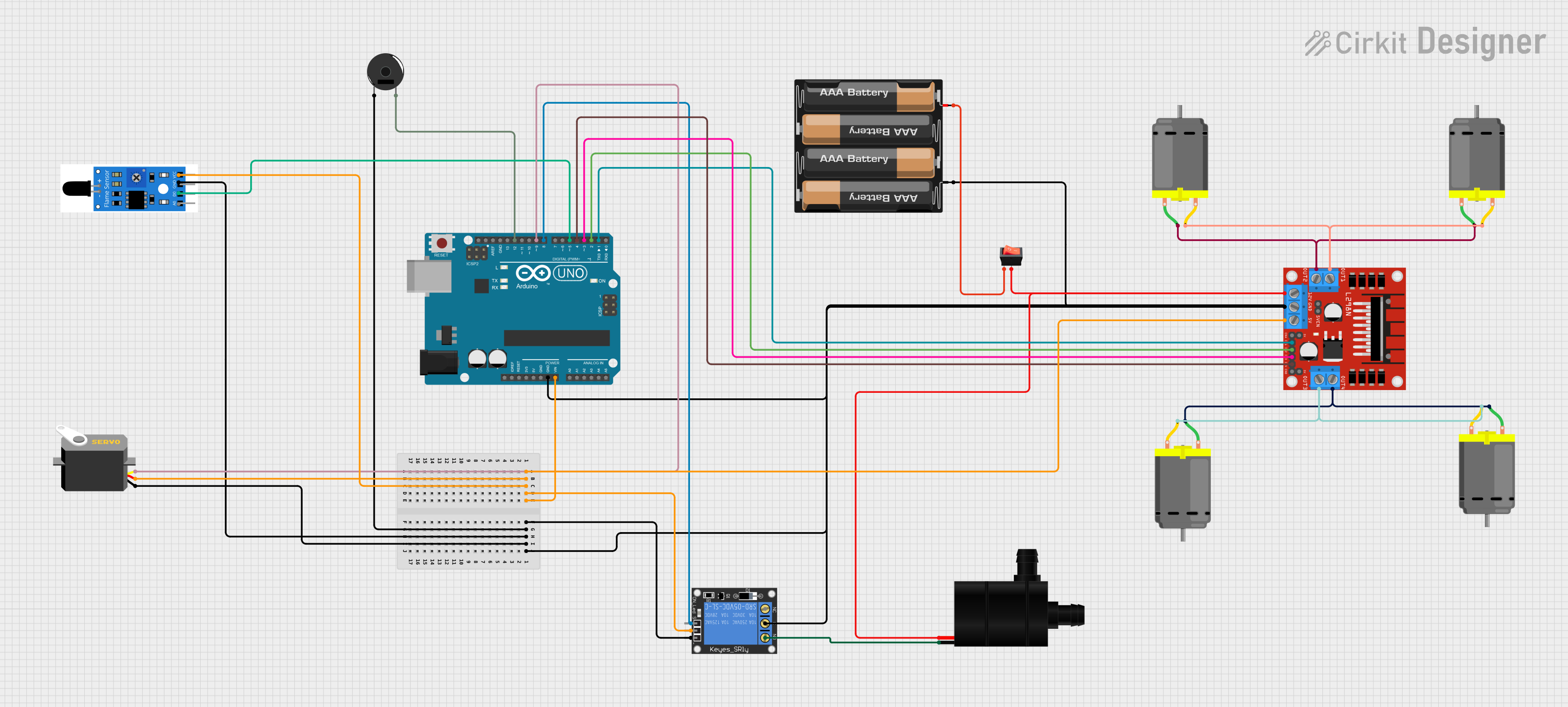
This circuit is designed to control various components including DC motors, a servo, a water pump, and a fire alarm, all managed by an Arduino UNO microcontroller. The circuit features a 1-Channel Relay to switch higher power loads, an L298N DC motor driver to control the motors, and a piezo buzzer for audio feedback. Power is supplied by a 4 x AAA battery mount, and a rocker switch is used to control the power flow. The fire alarm sensor is included for safety purposes, and its status is monitored by the Arduino UNO.
Component List
1-Channel Relay (5V 10A)
- A relay module that can control high power/high voltage devices.
- Pins: NC, signal, C, power, NO, ground
L298N DC Motor Driver
- A motor driver module capable of driving two DC motors.
- Pins: OUT1, OUT2, 12V, GND, 5V, OUT3, OUT4, 5V-ENA-JMP-I, 5V-ENA-JMP-O, +5V-J1, +5V-J2, ENA, IN1, IN2, IN3, IN4, ENB
DC Motor
- A standard DC motor used for motion applications.
- Pins: pin 1, pin 2
Servo
- A servo motor for precise control of angular position.
- Pins: gnd, vcc, pulse
Water Pump
- A pump for moving water, controlled by the relay.
- Pins: VCC, GND
Arduino UNO
- A microcontroller board based on the ATmega328P.
- Pins: UNUSED, IOREF, Reset, 3.3V, 5V, GND, Vin, A0-A5, SCL, SDA, AREF, D0-D13
Piezo Buzzer
- An electronic device that produces sound when an electrical signal is applied.
- Pins: pin 1, pin 2
4 x AAA Battery Mount
- A battery holder for four AAA batteries to provide power to the circuit.
- Pins: -, +
Fire Alarm
- A safety device that detects fire hazards.
- Pins: A0, D0, GND, VCC
Rocker Switch
- A switch to control the power supply to the circuit.
- Pins: output, input
Wiring Details
1-Channel Relay (5V 10A)
- Power: Connected to Arduino UNO Vin
- Ground: Connected to common ground
- Signal: Controlled by Arduino UNO D8
- Normally Open (NO): Connected to Water Pump VCC
L298N DC Motor Driver
- 5V: Powered by Arduino UNO Vin
- GND: Connected to common ground
- 12V: Controlled by rocker switch output
- IN1-IN4: Controlled by Arduino UNO D1-D4
- OUT1-OUT4: Connected to DC Motors
DC Motors
- Four DC motors connected in pairs to OUT1/OUT2 and OUT3/OUT4 of the L298N motor driver.
Servo
- VCC: Powered by Arduino UNO Vin
- GND: Connected to common ground
- Pulse: Controlled by Arduino UNO D9
Water Pump
- VCC: Connected to 1-Channel Relay NO
- GND: Connected to common ground
Arduino UNO
- Vin: Connected to 4 x AAA Battery Mount +
- GND: Connected to common ground
- D1-D12: Various controls for L298N, Piezo Buzzer, Servo, Relay, and Fire Alarm
Piezo Buzzer
- Pin 1: Connected to common ground
- Pin 2: Controlled by Arduino UNO D12
4 x AAA Battery Mount
- +: Connected to Arduino UNO Vin and rocker switch input
- -: Connected to common ground
Fire Alarm
- VCC: Powered by Arduino UNO Vin
- GND: Connected to common ground
- D0: Monitored by Arduino UNO D5
Rocker Switch
- Input: Connected to 4 x AAA Battery Mount +
- Output: Controls L298N 12V and Water Pump VCC
Documented Code
Arduino UNO Code (sketch.ino)
void setup() {
  // put your setup code here, to run once:

}

void loop() {
  // put your main code here, to run repeatedly:

}
Note: The provided code is a template and does not contain any functional code. It needs to be populated with the logic to control the components as per the circuit's requirements.