
Battery-Powered Light-Dependent Motor Control with L298N and LDRs
View and Edit Project In Cirkit Designer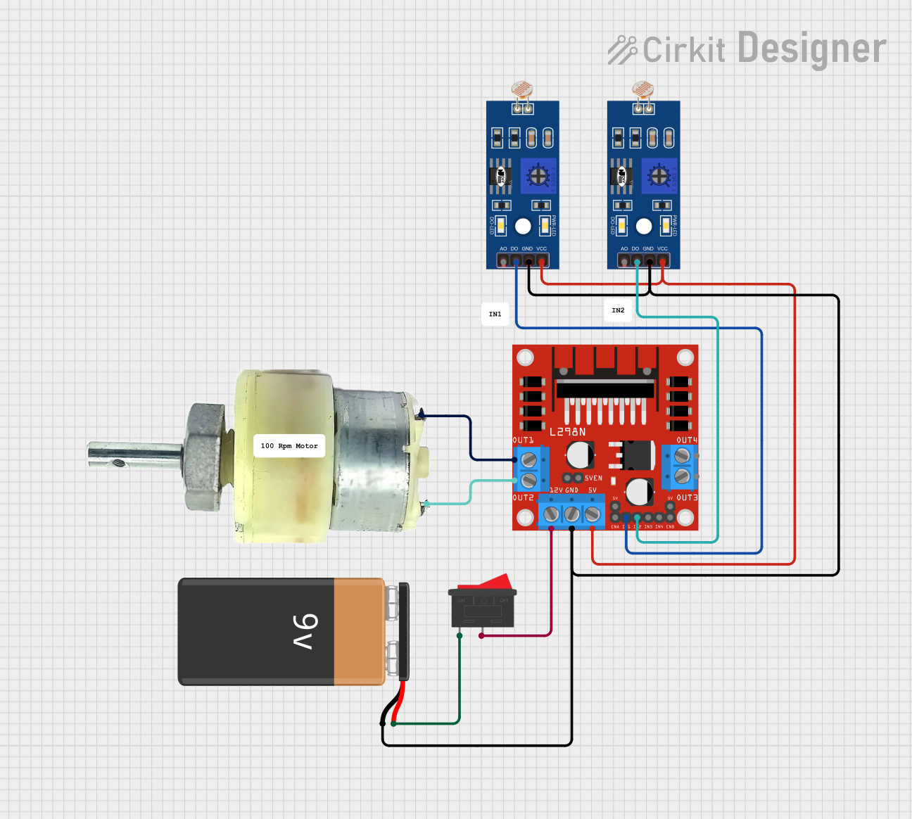
Circuit Documentation
Summary
This document provides a detailed overview of a circuit that includes a 9V battery, an L298N DC motor driver, two LDRs (Light Dependent Resistors), a 12V geared motor, and a rocker switch. The circuit is designed to control the motor based on the light intensity detected by the LDRs.
Component List
9V Battery
- Description: Provides the primary power source for the circuit.
- Pins: -, +
L298N DC Motor Driver
- Description: Controls the direction and speed of the DC motor.
- Pins: OUT1, OUT2, 12V, GND, 5V, OUT3, OUT4, 5V-ENA-JMP-I, 5V-ENA-JMP-O, +5V-J1, +5V-J2, ENA, IN1, IN2, IN3, IN4, ENB
LDR (Light Dependent Resistor)
- Description: Senses light intensity and provides an analog or digital output.
- Pins: A0, D0, GND, VCC
12V Geared Motor
- Description: Provides mechanical motion.
- Pins: Terminal 1, Terminal 2
Rocker Switch
- Description: Acts as an on/off switch for the circuit.
- Pins: 1, 2
Wiring Details
9V Battery
Pin - is connected to:
- GND of L298N DC motor driver
- GND of LDR (Instance 1)
- GND of LDR (Instance 2)
Pin + is connected to:
- Pin 1 of Rocker Switch
L298N DC Motor Driver
Pin GND is connected to:
- GND of 9V Battery
- GND of LDR (Instance 1)
- GND of LDR (Instance 2)
Pin 12V is connected to:
- Pin 2 of Rocker Switch
Pin 5V is connected to:
- VCC of LDR (Instance 1)
- VCC of LDR (Instance 2)
Pin OUT1 is connected to:
- Terminal 2 of 12V Geared Motor
Pin OUT2 is connected to:
- Terminal 1 of 12V Geared Motor
Pin IN1 is connected to:
- D0 of LDR (Instance 2)
Pin IN2 is connected to:
- D0 of LDR (Instance 1)
LDR (Instance 1)
Pin GND is connected to:
- GND of 9V Battery
- GND of L298N DC motor driver
- GND of LDR (Instance 2)
Pin VCC is connected to:
- 5V of L298N DC motor driver
Pin D0 is connected to:
- IN2 of L298N DC motor driver
LDR (Instance 2)
Pin GND is connected to:
- GND of 9V Battery
- GND of L298N DC motor driver
- GND of LDR (Instance 1)
Pin VCC is connected to:
- 5V of L298N DC motor driver
Pin D0 is connected to:
- IN1 of L298N DC motor driver
12V Geared Motor
Terminal 1 is connected to:
- OUT2 of L298N DC motor driver
Terminal 2 is connected to:
- OUT1 of L298N DC motor driver
Rocker Switch
Pin 1 is connected to:
-
- of 9V Battery
-
Pin 2 is connected to:
- 12V of L298N DC motor driver
Code
There is no microcontroller code provided for this circuit.