
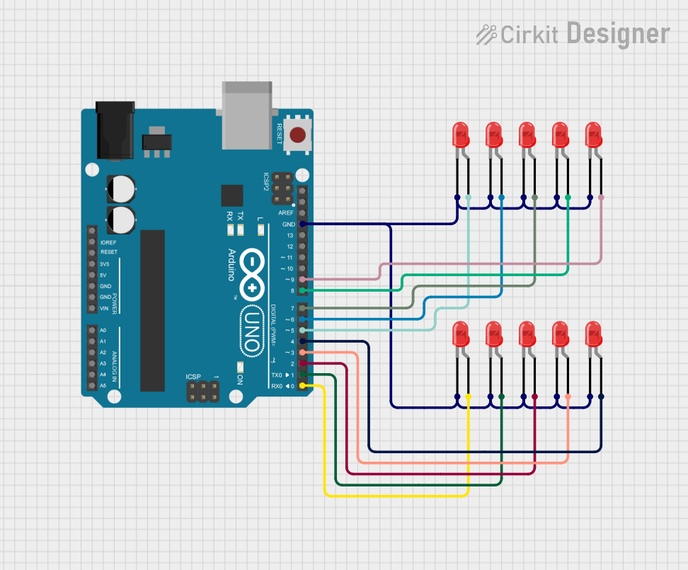
Circuit Documentation
Summary
The circuit consists of an Arduino UNO microcontroller connected to a series of ten red two-pin LEDs. The LEDs are controlled by the Arduino UNO, which sequentially turns each LED on and off with a delay between the transitions. The cathodes of all LEDs are connected to the ground (GND) pin of the Arduino, while the anodes are individually connected to digital pins D0 through D9.
Component List
Arduino UNO: A microcontroller board based on the ATmega328P. It has 14 digital input/output pins, 6 analog inputs, a 16 MHz quartz crystal, a USB connection, a power jack, an ICSP header, and a reset button.
LED: Two Pin (red): A basic red light-emitting diode with two pins: an anode and a cathode. The LED lights up when a forward current passes from the anode to the cathode.
Wiring Details
Arduino UNO
- GND: Connected to the cathodes of all LEDs.
- Digital Pins (D0 - D9): Each pin is connected to the anode of a single LED.
LED: Two Pin (red)
- Cathode: Connected to the GND pin of the Arduino UNO.
- Anode: Connected to one of the digital pins D0 - D9 on the Arduino UNO.
Documented Code
// Define the pin numbers for the LEDs
const int ledPins[] = {5, 6, 7, 8, 9, 0, 1, 2, 3, 4};
const int numLeds = sizeof(ledPins) / sizeof(ledPins[0]);

void setup() {
  // Initialize each pin as an output
  for (int i = 0; i < numLeds; i++) {
    pinMode(ledPins[i], OUTPUT);
  }
}

void loop() {
  // Turn each LED on and off sequentially
  for (int i = 0; i < numLeds; i++) {
    digitalWrite(ledPins[i], HIGH);  // Turn the LED on
    delay(500);                      // Wait for 500 milliseconds
    digitalWrite(ledPins[i], LOW);   // Turn the LED off
    delay(500);                      // Wait for 500 milliseconds
  }
}
Code Explanation
- ledPins[]: An array containing the digital pin numbers to which the LEDs are connected.
- numLeds: The number of LEDs, calculated based on the size of the
ledPinsarray. - setup(): A function that runs once when the microcontroller is powered on or reset. It initializes each pin in the
ledPinsarray as an output. - loop(): The main program loop that runs continuously after
setup(). It sequentially turns each LED on and off with a 500-millisecond delay between each state change.