
Wi-Fi Controlled Water Management System with ESP32 and Ultrasonic Sensor
View and Edit Project In Cirkit Designer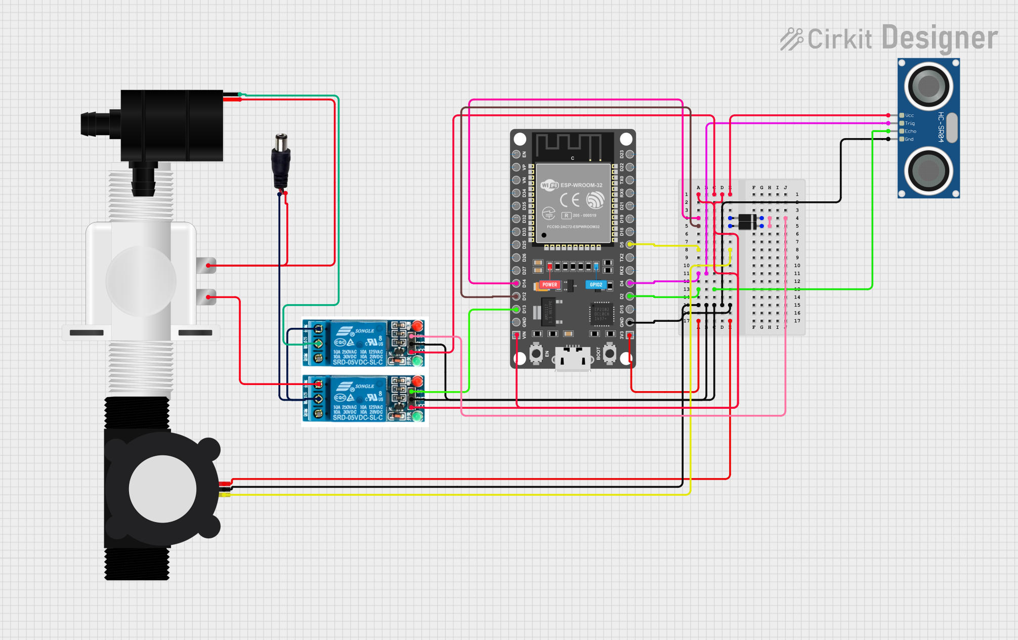
Circuit Documentation
Summary
This circuit integrates an ultrasonic sensor, a water flow sensor, a solenoid valve, a water pump, and relays controlled by an ESP32 microcontroller. The ultrasonic sensor measures distance to control relays, while the water flow sensor measures flow rate to control a solenoid valve. The ESP32 also hosts a web interface for setting a volume threshold for the water flow sensor.
Component List
HC-SR04 Ultrasonic Sensor
- Pins: VCC, TRIG, ECHO, GND
- Description: Measures distance using ultrasonic waves.
- Purpose in Circuit: Controls relays based on distance measurements.
Plastic Solenoid Valve
- Pins: pin1, pin2
- Description: Controls the flow of water.
- Purpose in Circuit: Opens or closes based on relay control.
ESP32 DEVKIT V1 (30 pins)
- Pins: EN, VP, VN, D34, D35, D32, D33, D25, D26, D27, D14, D12, D13, GND, VIN, 3V3, D15, D2, D4, RX2, TX2, D5, D18, D19, D21, RX0, TX0, D22, D23
- Description: Microcontroller with WiFi capabilities.
- Purpose in Circuit: Controls sensors and relays, hosts web interface.
5V Relay
- Pins: Normally Open, Common terminal, Normally Closed, In, GND, VCC
- Description: Electromechanical switch.
- Purpose in Circuit: Controls solenoid valve and water pump.
Power Jack
- Pins: POSITIF, NEGATIF
- Description: Provides power to the circuit.
- Purpose in Circuit: Supplies power to components.
Diode
- Pins: cathode, anode
- Description: Allows current to flow in one direction.
- Purpose in Circuit: Protects components from reverse voltage.
YF-S201 Water Flow Meter
- Pins: SIG, GND, VCC
- Description: Measures water flow rate.
- Purpose in Circuit: Provides flow rate data to the microcontroller.
Water Pump
- Pins: VCC, GND
- Description: Pumps water.
- Purpose in Circuit: Controlled by relay to pump water.
Wiring Details
HC-SR04 Ultrasonic Sensor
- VCC connected to VIN of ESP32.
- TRIG connected to D4 of ESP32.
- ECHO connected to D2 of ESP32.
- GND connected to GND of ESP32.
Plastic Solenoid Valve
- pin1 connected to Normally Open of 5V Relay.
- pin2 connected to NEGATIF of Power Jack.
ESP32 DEVKIT V1 (30 pins)
- VIN connected to VCC of HC-SR04, VCC of 5V Relay (both relays).
- D14 connected to anode of Diode.
- D12 connected to anode of another Diode.
- D5 connected to SIG of YF-S201 Water Flow Meter.
- D4 connected to TRIG of HC-SR04.
- D2 connected to ECHO of HC-SR04.
- GND connected to GND of HC-SR04, GND of 5V Relay (both relays), GND of YF-S201 Water Flow Meter.
- 3V3 connected to VCC of YF-S201 Water Flow Meter.
- D13 connected to In of 5V Relay.
- D12 connected to In of another 5V Relay.
5V Relay (First)
- VCC connected to VIN of ESP32.
- GND connected to GND of ESP32.
- In connected to D13 of ESP32.
- Normally Open connected to pin1 of Plastic Solenoid Valve.
- Common terminal connected to Normally Open of another 5V Relay.
- Normally Closed not connected.
5V Relay (Second)
- VCC connected to VIN of ESP32.
- GND connected to GND of ESP32.
- In connected to cathode of Diode.
- Normally Open connected to Common terminal of first 5V Relay.
- Common terminal connected to GND of Water Pump.
- Normally Closed not connected.
Power Jack
- POSITIF connected to Common terminal of first 5V Relay.
- NEGATIF connected to pin2 of Plastic Solenoid Valve.
Diode (First)
- anode connected to D14 of ESP32.
- cathode connected to cathode of another Diode, In of second 5V Relay.
Diode (Second)
- anode connected to D12 of ESP32.
- cathode connected to cathode of first Diode, In of second 5V Relay.
YF-S201 Water Flow Meter
- SIG connected to D5 of ESP32.
- GND connected to GND of ESP32.
- VCC connected to 3V3 of ESP32.
Water Pump
- VCC connected to pin2 of Plastic Solenoid Valve.
- GND connected to Common terminal of second 5V Relay.
Code Documentation
SWMS.ino
// This Arduino Sketch integrates an ultrasonic sensor and a water flow sensor.
// The ultrasonic sensor controls GPIO 13 and GPIO 12 based on distance.
// A web page allows the user to set a volume threshold for the water flow sensor.
// GPIO 14 is controlled based on the water flow sensor's readings.

#include <WiFi.h>
#include <WebServer.h>
#include "WebUI.h"

#define FLOW_SENSOR_PIN 5
#define TRIG_PIN 4
#define ECHO_PIN 2
#define RELAY_PIN_1 13
#define RELAY_PIN_2 12
#define RELAY_PIN_3 14

volatile int pulseCount = 0;
float flowRate = 0.0;
unsigned long oldTime = 0;
int volumeThreshold = 0;
WebServer server(80);

void IRAM_ATTR pulseCounter() {
  pulseCount++;
}

void handleRoot() {
  String html = "<form action='/setThreshold' method='POST'>";
  html += "Volume Threshold (mL): <input type='number' name='threshold'><br>";
  html += "<input type='submit' value='Apply'></form>";
  server.send(200, "text/html", html);
}

void handleSetThreshold() {
  if (server.hasArg("threshold")) {
    volumeThreshold = server.arg("threshold").toInt();
    server.send(200, "text/html", "Threshold set to " + String(volumeThreshold) + " mL");
  } else {
    server.send(400, "text/html", "Invalid Request");
  }
}

void setup() {
  Serial.begin(115200);
  pinMode(FLOW_SENSOR_PIN, INPUT);
  pinMode(TRIG_PIN, OUTPUT);
  pinMode(ECHO_PIN, INPUT);
  pinMode(RELAY_PIN_1, OUTPUT);
  pinMode(RELAY_PIN_2, OUTPUT);
  pinMode(RELAY_PIN_3, OUTPUT);
  attachInterrupt(digitalPinToInterrupt(FLOW_SENSOR_PIN), pulseCounter, RISING);
  oldTime = millis();
  WiFi.begin("yourSSID", "yourPASSWORD");
  while (WiFi.status() != WL_CONNECTED) {
    delay(1000);
    Serial.println("Connecting to WiFi...");
  }
  Serial.println("Connected to WiFi");
  server.on("/", handleRoot);
  server.on("/setThreshold", HTTP_POST, handleSetThreshold);
  server.begin();
}

void loop() {
  server.handleClient();
  unsigned long currentTime = millis();
  unsigned long elapsedTime = currentTime - oldTime;
  if (elapsedTime >= 1000) {
    flowRate = ((1000.0 / elapsedTime) * pulseCount) / 7.5;
    oldTime = currentTime;
    pulseCount = 0;
    Serial.printf("Flow rate: %.2f L/min\n", flowRate);
    if (flowRate * 1000 >= volumeThreshold) {
      digitalWrite(RELAY_PIN_3, LOW);
    } else {
      digitalWrite(RELAY_PIN_3, HIGH);
    }
  }
  digitalWrite(TRIG_PIN, LOW);
  delayMicroseconds(2);
  digitalWrite(TRIG_PIN, HIGH);
  delayMicroseconds(10);
  digitalWrite(TRIG_PIN, LOW);
  long duration = pulseIn(ECHO_PIN, HIGH);
  float