
Arduino UNO Based Smart Parking System with RFID Access and GSM Notifications
View and Edit Project In Cirkit Designer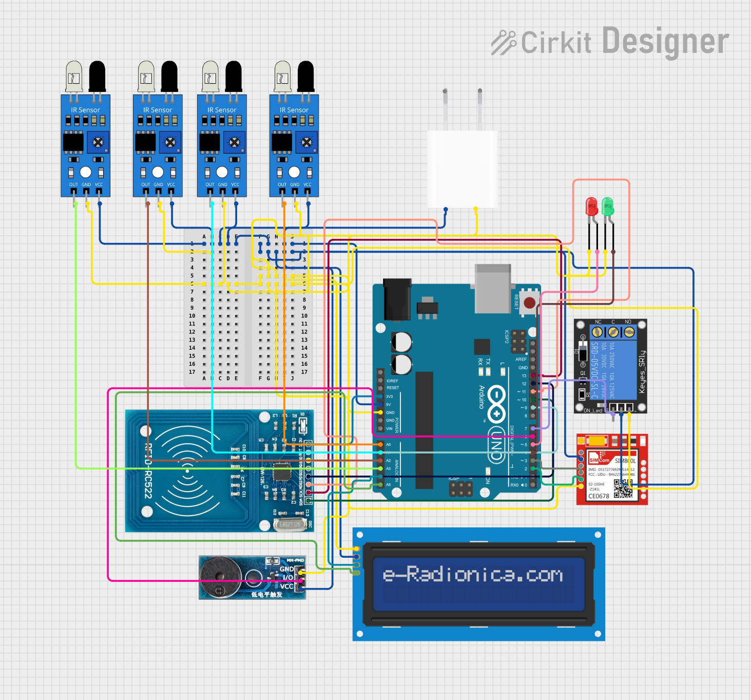
Circuit Documentation
Summary
This circuit is designed to manage a parking system with an RFID access control, SMS notifications, and visual indicators for parking availability. It includes an Arduino UNO microcontroller interfaced with various sensors and modules, such as IR sensors for parking spot detection, an RFID-RC522 module for access control, a GSM module for SMS communication, an LCD screen for displaying parking availability, a buzzer for audible alerts, a relay for gate control, and LEDs to indicate parking status.
Component List
- Buzzer Module: A module that produces sound when activated, used for audible alerts.
- LED (Red): A red light-emitting diode used as a visual indicator for parking status.
- LED (Green): A green light-emitting diode used as a visual indicator for parking availability.
- 5V Adapter: A power supply module that converts AC to a 5V DC output, used to power the circuit.
- Sim800l: A GSM/GPRS module that allows the microcontroller to communicate over a mobile network, used for sending SMS notifications.
- LCD screen 16x2 I2C: A 16x2 character LCD display with an I2C interface, used to show parking slot availability.
- Arduino UNO: A microcontroller board based on the ATmega328P, used as the central processing unit of the circuit.
- RFID-RC522: An RFID reader/writer module, used for access control via RFID cards.
- 1-Channel Relay (5V 10A): A relay module used to control the opening and closing of the parking gate.
- IR Sensors: Infrared sensors used to detect the presence of a vehicle in a parking spot.
Wiring Details
Buzzer Module
- Vcc: Connected to the 5V power rail.
- GND: Connected to the ground rail.
- I/O: Connected to Arduino UNO pin D6.
LED (Red)
- Cathode: Connected to the ground rail.
- Anode: Connected to Arduino UNO pin D5.
LED (Green)
- Cathode: Connected to the ground rail.
- Anode: Connected to Arduino UNO pin D4.
5V Adapter
- AC In 1 & AC In 2: Connected to the AC power source.
- 5V: Connected to the 5V power rail.
- GND: Connected to the ground rail.
Sim800l
- VCC: Connected to the 5V power rail.
- GND: Connected to the ground rail.
- RXD: Connected to Arduino UNO pin D2.
- TXD: Connected to Arduino UNO pin D3.
LCD screen 16x2 I2C
- VCC: Connected to the 5V power rail.
- GND: Connected to the ground rail.
- SDA: Connected to Arduino UNO pin A4.
- SCL: Connected to Arduino UNO pin A5.
Arduino UNO
- 5V & GND: Power rails for the circuit.
- Digital and Analog Pins: Connected to various components as per the functionality.
RFID-RC522
- VCC (3.3V): Connected to Arduino UNO pin 3.3V.
- RST: Connected to Arduino UNO pin D9.
- GND: Connected to the ground rail.
- IRQ: Not connected.
- MISO: Connected to Arduino UNO pin D12.
- MOSI: Connected to Arduino UNO pin D11.
- SCK: Connected to Arduino UNO pin D13.
- SDA: Connected to Arduino UNO pin D10.
1-Channel Relay (5V 10A)
- NC: Normally closed, not used in this circuit.
- Signal: Connected to Arduino UNO pin D7.
- C: Common, not used in this circuit.
- Power: Connected to the 5V power rail.
- NO: Normally open, controls the parking gate.
- Ground: Connected to the ground rail.
IR Sensors
- Vcc: Connected to the 5V power rail.
- GND: Connected to the ground rail.
- Out: Connected to Arduino UNO analog pins A0, A1, A2, and A3 respectively for each sensor.
Documented Code
#include <Wire.h>
#include <LiquidCrystal_I2C.h>
#include <SPI.h>
#include <MFRC522.h>
#include <SoftwareSerial.h>

#define SS_PIN 10
#define RST_PIN 9
MFRC522 rfid(SS_PIN, RST_PIN);  // Create RFID instance

SoftwareSerial GSM(2, 3); // GSM TX -> D2, GSM RX -> D3

LiquidCrystal_I2C lcd(0x27, 16, 2);  // LCD instance (I2C address is 0x27)

int relayPin = 7;  // Relay control pin
int greenLED = 4;  // Green LED for available parking
int redLED = 5;    // Red LED for parking full
int buzzerPin = 6; // Buzzer for alert

int irSensor1 = A0; // IR Sensor 1 for parking spot 1
int irSensor2 = A1; // IR Sensor 2 for parking spot 2
int irSensor3 = A2; // IR Sensor 3 for parking spot 3
int irSensor4 = A3; // IR Sensor 4 for parking spot 4

int slotAvailable = 4;  // Initial number of available slots
int threshold = 200;  // Threshold value to determine IR sensor detection

void setup() {
  pinMode(relayPin, OUTPUT);
  pinMode(greenLED, OUTPUT);
  pinMode(redLED, OUTPUT);
  pinMode(buzzerPin, OUTPUT);

  // Set IR sensors as input
  pinMode(irSensor1, INPUT);
  pinMode(irSensor2, INPUT);
  pinMode(irSensor3, INPUT);
  pinMode(irSensor4, INPUT);

  digitalWrite(relayPin, LOW);  // Keep relay off initially (parking gate closed)
  digitalWrite(greenLED, HIGH); // Parking is available initially
  digitalWrite(redLED, LOW);    // Red LED off (parking not full)

  lcd.init();  // Initialize LCD
  lcd.backlight();  // Turn on LCD backlight
  lcd.setCursor(0, 0);
  lcd.print("Slot Available:");
  lcd.setCursor(0, 1);
  lcd.print(slotAvailable);

  SPI.begin();  // Initialize SPI bus for RFID reader
  rfid.PCD_Init();

  GSM.begin(9600);  // Start GSM communication
  Serial.begin(9600);  // Start Serial for debugging
}

void loop() {
  // Check if any parking spot is occupied
  checkIRSensors();

  // Check for RFID card presence
  if (!rfid.PICC_IsNewCardPresent() || !rfid.PICC_ReadCardSerial()) {
    return;
  }

  // Assuming every scanned RFID is valid for this example
  if (slotAvailable > 0) {
    slotAvailable--;  // Decrease available slot count

    // If there are available slots, open the gate and alert
    digitalWrite(relayPin, HIGH);  // Open the parking gate
    digitalWrite(buzzerPin, HIGH); // Sound buzzer
    delay(1000);
    digitalWrite(buzzerPin, LOW);  // Turn off buzzer after 1 second
    delay(5000);  // Keep gate open for 5 seconds
    digitalWrite(relayPin, LOW);  // Close the gate

    // Update LCD with available slots
    lcd.setCursor(0, 0);
    lcd.print("Slot Available: ");
    lcd.setCursor(0, 1);
    lcd.print(slotAvailable);

    // Send SMS notification when parking slot is occupied
    sendSMS(slotAvailable);
  }

  rfid.PICC_HaltA();  // Stop reading RFID card
}

// Function to check the IR sensors for occupied parking spots
void checkIRSensors() {
  int ir1 = analogRead(irSensor1);
  int ir2 = analogRead(irSensor2);
  int ir3 = analogRead(irSensor3);
  int ir4 = analogRead(irSensor4);

  if (ir1 < threshold || ir2 < threshold || ir3 < threshold || ir4 < threshold) {
    digitalWrite(greenLED, HIGH);  // If any slot is available, turn on green LED
    digitalWrite(redLED, LOW);     // Parking is not full, turn off red LED
  } else {
    digitalWrite(greenLED, LOW);   // If no slots available, turn off green LED
    digitalWrite(redLED, HIGH);    // Parking full, turn on red LED
    lcd.setCursor(0, 0);
    lcd.print("Parking Full!   ");
    lcd.setCursor(0, 1);
    lcd.print("No Slots        ");
  }
}

// Function to send SMS using GSM module
void sendSMS(int availableSlots) {
  GSM.print("AT+CMGF=1\r");  // Set SMS mode to text
  delay(1000);
  GSM.print("AT+CMGS=\"+1234567890\"\r");  // Replace with your phone number
  delay(1000);
  GSM.print