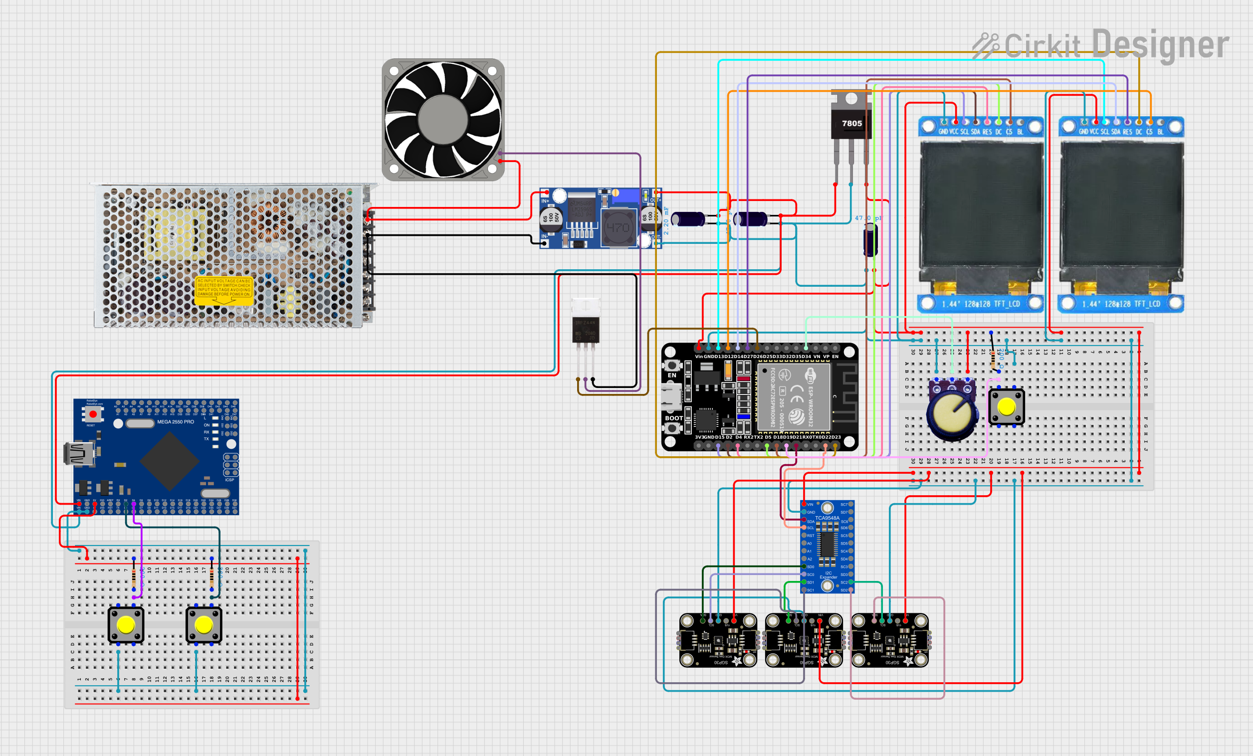
Multi-Sensor Environmental Monitoring System with Dual-Display Output

Circuit Documentation
Summary
This circuit appears to be designed for environmental sensing, display, and control applications. It includes sensors for air quality monitoring, a microcontroller for processing sensor data, a display for user interface, power regulation components, and user input buttons. The circuit uses an ESP32 microcontroller as the main processing unit, which communicates with an Adafruit SGP30 air quality sensor and controls a TFT display. A Mega2560 R3 Pro CH340G microcontroller is also included, possibly for additional control or interfacing tasks. Power regulation is achieved through a combination of a switching power supply, a buck converter, and a 7805 voltage regulator. User inputs are handled by pushbuttons, and a potentiometer is included, likely for analog input. An IRFZ44N MOSFET is used to control a 12V fan, and various capacitors are used for filtering and decoupling purposes.
Component List
Sensors
- Adafruit SGP30: An air quality sensor capable of measuring volatile organic compounds (VOCs) and equivalent CO2 (eCO2) levels.
Displays
- ST7735 128x128 1.44" TFT I2C Color: A small TFT display with 128x128 pixel resolution, used for displaying sensor data or user interface elements.
Microcontrollers
- ESP32 (30 pin): A powerful microcontroller with Wi-Fi and Bluetooth capabilities, used as the main processing unit in this circuit.
- Mega2560 R3 Pro CH340G: An additional microcontroller based on the ATmega2560, possibly used for extended I/O capabilities or separate tasks.
Power Regulation
- 7805: A voltage regulator that outputs a steady 5V from a higher voltage input.
- Buck Converter: A DC-DC converter used to step down voltage efficiently.
- Switching Power Supply: Converts AC mains power to a stable DC output, likely providing power to the entire circuit.
User Input
- Pushbutton: A simple switch used for user input.
- Potentiometer: Provides variable resistance, typically used for analog input such as setting thresholds or adjusting settings.
Control
- IRFZ44N: A power MOSFET used for switching high current loads, such as a fan or other actuators.
Passive Components
- Electrolytic Capacitor: Used for filtering and stabilizing voltage levels in the circuit.
- Resistor: Used to limit current or divide voltages in various parts of the circuit.
Communication
- Adafruit TCA9548A: An I2C multiplexer that allows multiple I2C devices with the same address to be connected to a single microcontroller.
Actuators
- 40 Fan 12v: A 12V fan controlled by the circuit, likely for cooling or airflow purposes.
Wiring Details
Adafruit SGP30 (Air Quality Sensor)
- VCC: Connected to 5V power supply.
- GND: Connected to the ground plane.
- SCL: Connected to the I2C clock line via an I2C multiplexer.
- SDA: Connected to the I2C data line via an I2C multiplexer.
ST7735 128x128 1.44" TFT I2C Color (Display)
- VCC: Connected to 5V power supply.
- GND: Connected to the ground plane.
- SCL: Connected to the I2C clock line of the ESP32.
- SDA: Connected to the I2C data line of the ESP32.
- RES: Connected to a digital output on the ESP32 for reset control.
- DC: Connected to a digital output on the ESP32 for data/command selection.
- C5: Connected to a digital output on the ESP32 for additional control.
ESP32 (30 pin) (Microcontroller)
- Vin: Connected to 5V power supply.
- GND: Connected to the ground plane.
- EN: Enable pin, typically connected to a pull-up resistor or left unconnected for normal operation.
- 3V3: 3.3V output, can be used to power other 3.3V components.
- GPIOs: Various GPIO pins are connected to the TFT display, potentiometer, and IRFZ44N gate.
Mega2560 R3 Pro CH340G (Microcontroller)
- Vin: Connected to 5V power supply.
- GND: Connected to the ground plane.
- Digital Pins: Connected to pushbuttons and their associated resistors.
Power Regulation Components
7805 (Voltage Regulator)
- Vin: Connected to the output of the buck converter.
- Gnd: Connected to the ground plane.
- Vout: Provides a regulated 5V output to the circuit.
Buck Converter
- IN+: Connected to the positive voltage output of the switching power supply.
- IN-: Connected to the ground plane.
- OUT+: Provides a stepped-down voltage to the 7805 regulator.
- OUT-: Connected to the ground plane.
Switching Power Supply
- AC: Connected to the AC mains.
- GND: Connected to the ground plane.
- -V: Connected to the ground plane.
- +V: Provides DC power to the buck converter and directly to the IRFZ44N MOSFET.
User Input Components
Pushbutton
- One side connected to a digital input on the Mega2560 with a pull-up resistor.
- The other side connected to the ground plane.
Potentiometer
- VCC: Connected to 5V power supply.
- GND: Connected to the ground plane.
- Output: Connected to an analog input on the ESP32.
IRFZ44N (MOSFET)
- Gate: Connected to a digital output on the ESP32.
- Drain: Connected to the negative terminal of the 12V fan.
- Source: Connected to the negative output of the buck converter.
Electrolytic Capacitor
- Connected across the power supply lines near the voltage regulator and microcontrollers for decoupling.
Resistor
- Connected in series with pushbuttons and used as pull-up resistors for the MOSFET gate.
Documented Code
No code was provided for the microcontrollers in the circuit. Typically, the code would include initialization routines for the microcontroller peripherals (e.g., I2C, GPIO), logic for reading sensor data, controlling the display, and responding to user inputs. It would also contain the control algorithm for the fan based on sensor readings or user settings.