
Battery-Powered Robotic System with Raspberry Pi Pico and Motor Driver
View and Edit Project In Cirkit Designer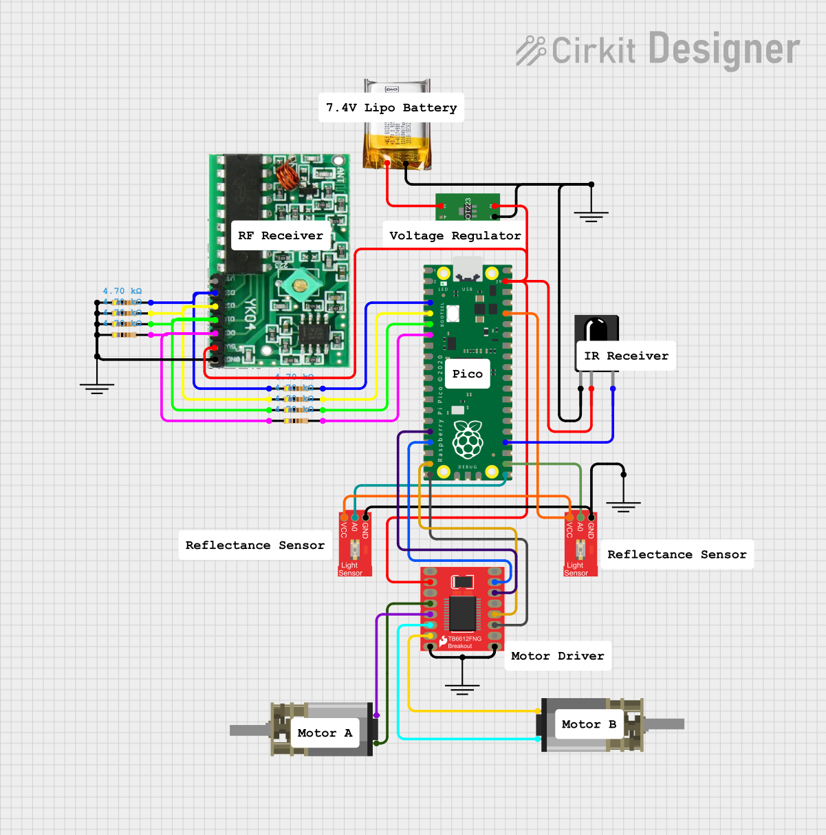
Circuit Documentation
Summary
This document provides a detailed overview of a circuit that includes various sensors, motors, and a microcontroller. The circuit is designed to interface with a Raspberry Pi Pico, which controls the components based on input from sensors and other devices. The circuit includes an IR receiver, light sensors, a motor driver, and a 433MHz RF receiver, among other components.
Component List
TSOP312 IR Receiver
- Pins: GND, Vs, Data
- Description: An IR receiver module used to receive infrared signals.
ProtoSnap - Pro Mini - Light Sensor
- Pins: VCC, A0, GND
- Description: A light sensor module used to detect ambient light levels.
Resistor (4700 Ohms)
- Pins: pin1, pin2
- Description: A resistor with a resistance of 4700 Ohms.
DC Mini Metal Gear Motor
- Pins: IN1, IN2
- Description: A small DC motor with metal gears.
GND
- Pins: GND
- Description: Ground connection.
RF YK04 433MHz Receiver
- Pins: Vt, D3, D2, D1, D0, 5V, GND
- Description: A 433MHz RF receiver module.
Motor Driver 1A Dual TB6612FNG
- Pins: GND, B01, B02, A02, A01, VCC, VM, PWMA, AIN2, AIN1, STBY, BIN1, BIN2, PWMB
- Description: A dual motor driver module capable of driving two motors.
Raspberry Pi Pico
- Pins: pin 1 to pin 43
- Description: A microcontroller board based on the RP2040 microcontroller chip.
Voltage Regulator
- Pins: ADJ, OUT, IN
- Description: A voltage regulator used to provide a stable output voltage.
3.7v LiPo
- Pins: +Ve, GND
- Description: A 3.7V Lithium Polymer battery.
Wiring Details
TSOP312 IR Receiver
- GND connected to GND of the Voltage Regulator.
- Vs connected to OUT of the Voltage Regulator.
- Data connected to pin 24 of the Raspberry Pi Pico.
ProtoSnap - Pro Mini - Light Sensor
- VCC connected to pin 36 of the Raspberry Pi Pico.
- A0 connected to pin 21 of the Raspberry Pi Pico.
- GND connected to GND of the Raspberry Pi Pico.
Resistor (4700 Ohms)
- pin2 connected to pin 4 of the Raspberry Pi Pico.
- pin2 connected to pin 5 of the Raspberry Pi Pico.
- pin2 connected to pin 6 of the Raspberry Pi Pico.
- pin2 connected to pin 7 of the Raspberry Pi Pico.
- pin2 connected to D3 of the RF YK04 433MHz Receiver.
- pin2 connected to D2 of the RF YK04 433MHz Receiver.
- pin2 connected to D1 of the RF YK04 433MHz Receiver.
- pin2 connected to D0 of the RF YK04 433MHz Receiver.
- pin1 connected to GND of the RF YK04 433MHz Receiver.
DC Mini Metal Gear Motor
- IN1 connected to B01 of the Motor Driver 1A Dual TB6612FNG.
- IN2 connected to B02 of the Motor Driver 1A Dual TB6612FNG.
- IN1 connected to A01 of the Motor Driver 1A Dual TB6612FNG.
- IN2 connected to A02 of the Motor Driver 1A Dual TB6612FNG.
GND
- GND connected to GND of the Voltage Regulator.
- GND connected to GND of the RF YK04 433MHz Receiver.
- GND connected to GND of the Raspberry Pi Pico.
RF YK04 433MHz Receiver
- 5V connected to OUT of the Voltage Regulator.
- GND connected to GND of the Voltage Regulator.
- D3 connected to pin2 of a Resistor.
- D2 connected to pin2 of a Resistor.
- D1 connected to pin2 of a Resistor.
- D0 connected to pin2 of a Resistor.
Motor Driver 1A Dual TB6612FNG
- AIN1 connected to pin 16 of the Raspberry Pi Pico.
- AIN2 connected to pin 17 of the Raspberry Pi Pico.
- BIN1 connected to pin 19 of the Raspberry Pi Pico.
- BIN2 connected to pin 20 of the Raspberry Pi Pico.
- VCC connected to OUT of the Voltage Regulator.
- GND connected to GND of the Voltage Regulator.
Raspberry Pi Pico
- pin 4 connected to pin2 of a Resistor.
- pin 5 connected to pin2 of a Resistor.
- pin 6 connected to pin2 of a Resistor.
- pin 7 connected to pin2 of a Resistor.
- pin 16 connected to AIN1 of the Motor Driver 1A Dual TB6612FNG.
- pin 17 connected to AIN2 of the Motor Driver 1A Dual TB6612FNG.
- pin 19 connected to BIN1 of the Motor Driver 1A Dual TB6612FNG.
- pin 20 connected to BIN2 of the Motor Driver 1A Dual TB6612FNG.
- pin 21 connected to A0 of the ProtoSnap - Pro Mini - Light Sensor.
- pin 22 connected to A0 of another ProtoSnap - Pro Mini - Light Sensor.
- pin 24 connected to Data of the TSOP312 IR Receiver.
- pin 36 connected to VCC of the ProtoSnap - Pro Mini - Light Sensor.
- pin 39 connected to OUT of the Voltage Regulator.
Voltage Regulator
- IN connected to +Ve of the 3.7v LiPo.
- OUT connected to VCC of the Motor Driver 1A Dual TB6612FNG.
- OUT connected to Vs of the TSOP312 IR Receiver.
- OUT connected to 5V of the RF YK04 433MHz Receiver.
- OUT connected to pin 39 of the Raspberry Pi Pico.
- ADJ connected to GND of the 3.7v LiPo.
3.7v LiPo
- +Ve connected to IN of the Voltage Regulator.
- GND connected to GND of the Voltage Regulator.
Documented Code
Raspberry Pi Pico Code (sketch.ino)
void setup() {
  // put your setup code here, to run once:

}

void loop() {
  // put your main code here, to run repeatedly:

}
Documentation (documentation.txt)
This document provides a comprehensive overview of the circuit, including a detailed list of components, their wiring connections, and the code used for the Raspberry Pi Pico.