Arduino UNO R4 WiFi Controlled Weather Station with LCD Display
Circuit Documentation
Summary of the Circuit
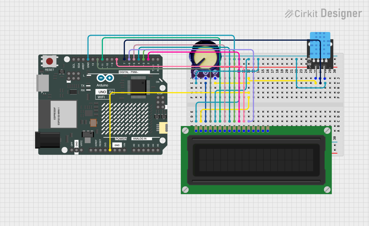
This circuit integrates an Arduino UNO R4 WiFi with an LCD Display (16 pin), a DHT11 temperature and humidity sensor, and a potentiometer. The Arduino serves as the central microcontroller, interfacing with the LCD to display information and reading data from the DHT11 sensor. The potentiometer is used to adjust the contrast of the LCD display. The circuit is designed to be powered by the Arduino's 5V output, which is distributed to the other components.
Component List
Arduino UNO R4 WiFi
- Description: A microcontroller board based on the ATmega328, with integrated WiFi capabilities.
- Pins: OFF, GND, VRTC, IIC0_SCL, IIC0_SDA, 3V3, GPIO 41, GPIO 0, GPIO 42, GPIO 43, GPIO 44, BOOT, IOREF, RESET, 5V, VIN, A0, A1, A2, A3, A4, A5, RSPCKA, CIPO, COPI, D0/RX, D1/TX, D2, D3, D4, D5, D6, D7, D8, D9, D10, D11, D12, D13, AREF, SDA, SCL
LCD Display (16 pin)
- Description: A 16x2 character LCD display module for displaying text or simple graphics.
- Pins: VSS, VDD, VO, RS, R_W, E, DB0, DB1, DB2, DB3, DB4, DB5, DB6, DB7, A, K
DHT11
- Description: A basic, ultra low-cost digital temperature and humidity sensor.
- Pins: 5V, S, GND
Potentiometer
- Description: A three-terminal resistor with a continuously adjustable tapping point controlled by rotation of a shaft or knob.
- Pins: GND, Output, VCC
Wiring Details
Arduino UNO R4 WiFi
- 5V: Provides power to the LCD Display, DHT11, and Potentiometer.
- GND: Common ground for the LCD Display, DHT11, and Potentiometer.
- D2: Connected to DB3 of the LCD Display.
- D3: Connected to DB2 of the LCD Display.
- D4: Connected to DB1 of the LCD Display.
- D5: Connected to DB0 of the LCD Display.
- D6: Connected to DB5 of the LCD Display.
- D7: Connected to the signal pin (S) of the DHT11.
- D8: Connected to DB4 of the LCD Display.
- D11: Connected to the enable pin (E) of the LCD Display.
- D12: Connected to the register select pin (RS) of the LCD Display.
LCD Display (16 pin)
- VDD: Connected to the 5V output from the Arduino.
- VSS: Connected to the ground (GND) on the Arduino.
- VO: Connected to the output of the Potentiometer for contrast adjustment.
- RS, E, DB0-DB5: Connected to various digital pins on the Arduino for data/command transmission.
DHT11
- 5V: Connected to the 5V output from the Arduino.
- S: Connected to digital pin D7 on the Arduino for data transmission.
- GND: Connected to the ground (GND) on the Arduino.
Potentiometer
- VCC: Connected to the 5V output from the Arduino.
- Output: Connected to the VO pin on the LCD Display for contrast control.
- GND: Connected to the ground (GND) on the Arduino.
Documented Code
void setup() {
  // put your setup code here, to run once:

}

void loop() {
  // put your main code here, to run repeatedly:

}
The provided code is a template for the Arduino sketch with empty setup() and loop() functions. The setup() function is intended for initialization code that runs once at the start, while the loop() function contains code that runs repeatedly, forming the main logic of the program. The user is expected to fill in these functions with code to initialize the LCD display, read data from the DHT11 sensor, and display the information on the LCD.