
Circuit Documentation
Summary
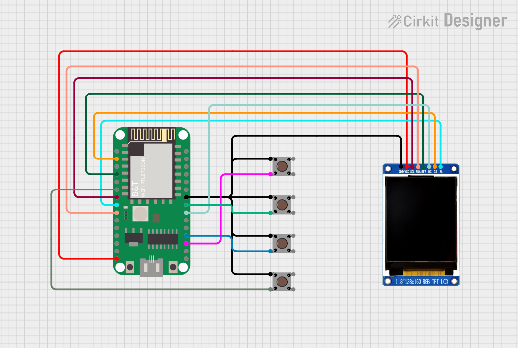
This circuit involves an RTL8720DN microcontroller interfaced with a China ST7735S 160x128 TFT LCD display and four pushbuttons. The microcontroller reads the states of the pushbuttons and displays their statuses on the TFT LCD. The circuit is designed to demonstrate basic input reading and display output using an embedded system.
Component List
RTL8720DN Microcontroller
- Description: A low-power, high-performance microcontroller with multiple GPIO pins.
- Pins: PA15(pin4), CHIP-EN, 3V3, GND, PA12(pin12), PA30(pin3), PA27(pin2), PA14(pin10), PA13(pin11), PA8(pin1), PA26(pin8), NC, VIN, PB2(pin5), PA7(pin0), PA25(pin7), PB3(pin6), PB1(pin4)
Pushbutton (4 instances)
- Description: A simple pushbutton used for user input.
- Pins: Pin 3 (out), Pin 4 (out), Pin 1 (in), Pin 2 (in)
China ST7735S 160x128 TFT LCD Display
- Description: A 160x128 pixel TFT LCD display module.
- Pins: GND, VCC, SCL, SDA, RES, DC, CS, BL
Wiring Details
RTL8720DN Microcontroller
- PA12(pin12): Connected to SDA pin of the TFT LCD.
- PA30(pin3): Connected to BL pin of the TFT LCD.
- PA27(pin2): Connected to CS pin of the TFT LCD.
- PA14(pin10): Connected to SCL pin of the TFT LCD.
- PA13(pin11): Connected to Pin 1 (in) of a pushbutton.
- PA26(pin8): Connected to RES pin of the TFT LCD.
- VIN: Connected to VCC pin of the TFT LCD.
- PB2(pin5): Connected to Pin 1 (in) of a pushbutton.
- PA25(pin7): Connected to DC pin of the TFT LCD.
- PB3(pin6): Connected to Pin 1 (in) of a pushbutton.
- GND: Connected to GND pin of the TFT LCD and Pin 3 (out) of all pushbuttons.
- PB1(pin4): Connected to Pin 1 (in) of a pushbutton.
Pushbutton 1
- Pin 1 (in): Connected to PB1(pin4) of the RTL8720DN.
- Pin 3 (out): Connected to GND pin of the RTL8720DN.
Pushbutton 2
- Pin 1 (in): Connected to PB3(pin6) of the RTL8720DN.
- Pin 3 (out): Connected to GND pin of the RTL8720DN.
Pushbutton 3
- Pin 1 (in): Connected to PB2(pin5) of the RTL8720DN.
- Pin 3 (out): Connected to GND pin of the RTL8720DN.
Pushbutton 4
- Pin 1 (in): Connected to PA13(pin11) of the RTL8720DN.
- Pin 3 (out): Connected to GND pin of the RTL8720DN.
China ST7735S 160x128 TFT LCD Display
- SDA: Connected to PA12(pin12) of the RTL8720DN.
- BL: Connected to PA30(pin3) of the RTL8720DN.
- CS: Connected to PA27(pin2) of the RTL8720DN.
- SCL: Connected to PA14(pin10) of the RTL8720DN.
- RES: Connected to PA26(pin8) of the RTL8720DN.
- VCC: Connected to VIN pin of the RTL8720DN.
- DC: Connected to PA25(pin7) of the RTL8720DN.
- GND: Connected to GND pin of the RTL8720DN and Pin 3 (out) of all pushbuttons.
Code Documentation
#include <Adafruit_GFX.h>
#include <Adafruit_ST7735.h>

// Pin Definition for LCD
#define TFT_SCLK PA14 // clock
#define TFT_MOSI PA12 // data
#define TFT_RES PA26 // reset
#define TFT_DC PA25 // data/command
#define TFT_CS PA27 // chip select
#define TFT_BL PA30 // backlight

// button pin definition
#define BUTTON_1 PB1
#define BUTTON_2 PB3
#define BUTTON_3 PB2
#define BUTTON_4 PA13

// create TFT LCD object
Adafruit_ST7735 tft = Adafruit_ST7735(TFT_CS, TFT_DC, TFT_MOSI, TFT_SCLK, TFT_RES);

void setup() {
  // initialize serial monitor
  Serial.begin(115200);

  // initialize buttons as input
  pinMode(BUTTON_1, INPUT_PULLUP);
  pinMode(BUTTON_2, INPUT_PULLUP);
  pinMode(BUTTON_3, INPUT_PULLUP);
  pinMode(BUTTON_4, INPUT_PULLUP);

  // initialize backlight as output
  pinMode(TFT_BL, OUTPUT);
  digitalWrite(TFT_BL, HIGH); // turn on backlight

  // initialize TFT LCD
  tft.initR(INITR_BLACKTAB); // initialize with ST7735 black tab
  tft.fillScreen(ST77XX_BLACK);
  tft.setRotation(1); // set rotation
  tft.setTextColor(ST77XX_WHITE);
  tft.setTextSize(1);

  // welcome message
  tft.setCursor(0, 0);
  tft.println("TFT LCD Initialized!");
  tft.println("Buttons Ready");
}

void loop() {
  // read button states
  bool button1State = digitalRead(BUTTON_1) == LOW;
  bool button2State = digitalRead(BUTTON_2) == LOW;
  bool button3State = digitalRead(BUTTON_3) == LOW;
  bool button4State = digitalRead(BUTTON_4) == LOW;

  // display button states on TFT
  tft.fillRect(0, 20, 128, 140, ST77XX_BLACK); // clear previous text
  tft.setCursor(0, 20);

  tft.println("Button States:");
  tft.println("Button 1: "); tft.println(button1State ? "PRESSED" : "RELEASED");
  tft.println("Button 2: "); tft.println(button2State ? "PRESSED" : "RELEASED");
  tft.println("Button 3: "); tft.println(button3State ? "PRESSED" : "RELEASED");
  tft.println("Button 4: "); tft.println(button4State ? "PRESSED" : "RELEASED");

  // add a small delay to avoid flickering
  delay(100);
}
This code initializes the TFT LCD and the pushbuttons, reads the states of the pushbuttons, and displays their statuses on the TFT LCD. The backlight of the TFT LCD is also controlled by the microcontroller.