
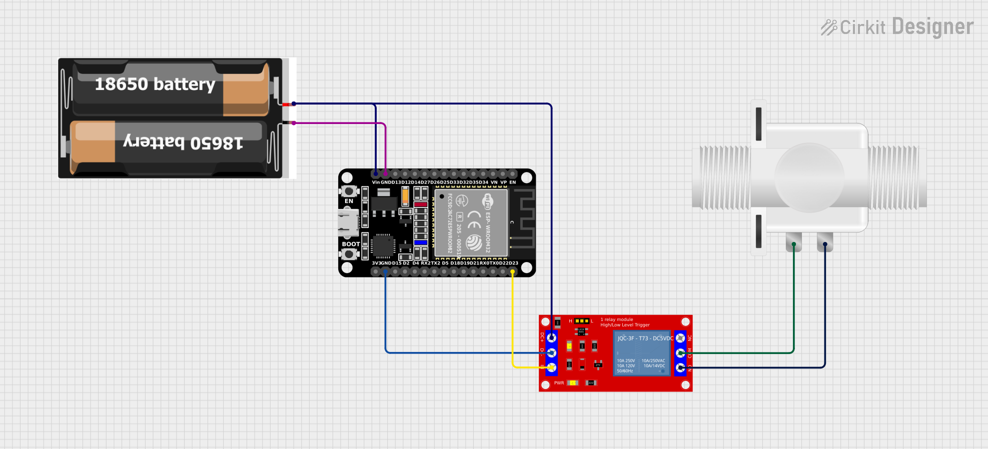
Circuit Documentation
Summary of the Circuit
This circuit is designed to control a plastic solenoid valve using an ESP32 microcontroller and a 1-channel 5V relay module. The ESP32 is powered by a 2x 18650 battery pack. The relay module acts as an intermediary, allowing the ESP32 to control the high-power solenoid valve safely. The ESP32's GPIO pin is used to trigger the relay, which in turn controls the power to the solenoid valve. The ground connections are shared among the ESP32, the relay module, and the battery pack to complete the circuit.
Component List
ESP32 (30 pin)
- Description: A microcontroller with Wi-Fi and Bluetooth capabilities, featuring a wide range of GPIO pins.
- Pins: EN, VP, VN, D34, D35, D32, D33, D25, D26, D27, D14, D12, D13, GND, Vin, D23, D22, TX0, RX0, D21, D19, D18, D5, TX2, RX2, D4, D2, D15, 3V3
1 Channel 5V Relay Module
- Description: A relay module that allows a low-power signal to switch a higher power circuit on and off.
- Pins: VCC+, VCC- (GND), IN, N.O., COM, N.C.
2x 18650 Battery Pack
- Description: A battery pack consisting of two 18650 batteries providing a power source for the circuit.
- Pins: vcc, gnd
Plastic Solenoid Valve
- Description: An electrically-controlled valve used for controlling the flow of a liquid or gas.
- Pins: pin1, pin2
Wiring Details
ESP32 (30 pin)
- GND connected to the ground (gnd) of the 2x 18650 battery pack.
- Vin connected to the VCC+ of the 1 Channel 5V Relay Module and vcc of the 2x 18650 battery pack.
- D23 connected to the IN pin of the 1 Channel 5V Relay Module.
1 Channel 5V Relay Module
- VCC+ connected to the Vin of the ESP32 and vcc of the 2x 18650 battery pack.
- VCC- (GND) connected to the GND of the ESP32.
- IN connected to the D23 pin of the ESP32.
- N.O. connected to pin2 of the Plastic Solenoid Valve.
- COM connected to pin1 of the Plastic Solenoid Valve.
2x 18650 Battery Pack
- vcc connected to the Vin of the ESP32 and VCC+ of the 1 Channel 5V Relay Module.
- gnd connected to the GND of the ESP32.
Plastic Solenoid Valve
- pin1 connected to the COM pin of the 1 Channel 5V Relay Module.
- pin2 connected to the N.O. pin of the 1 Channel 5V Relay Module.
Documented Code
There is no code provided for the microcontroller in this circuit. The ESP32 would typically be programmed to control the relay module by setting GPIO pin D23 as an output and toggling it to activate the relay, which would in turn control the solenoid valve. However, without the actual code, we cannot provide further documentation on the software aspect of this circuit.