Cirkit Designer
Your all-in-one circuit design IDE
Home /
Project Documentation
Arduino UNO Countdown Timer with 7-Segment Display and Alert System
Circuit Documentation
Summary
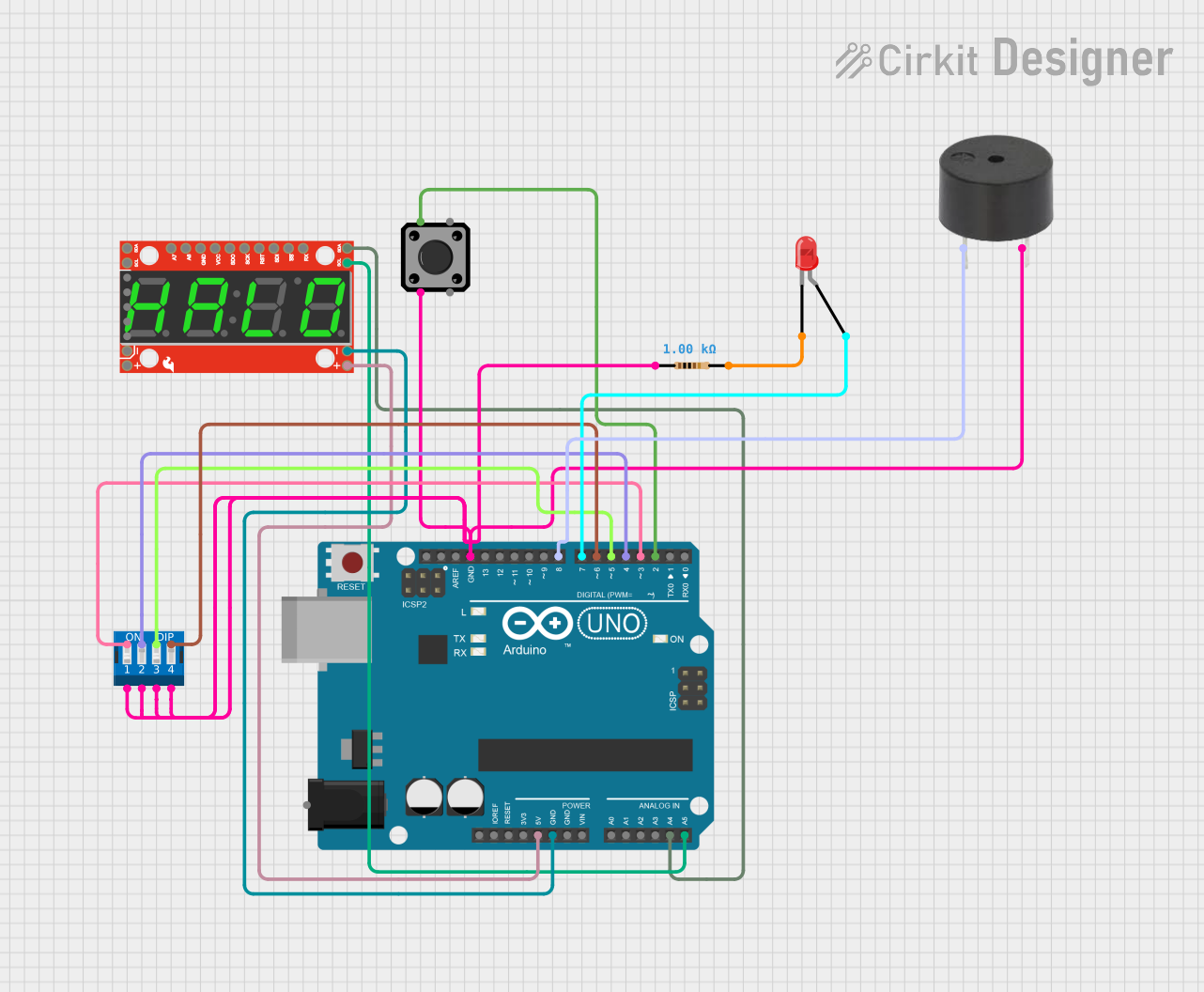
This circuit is designed to interface an Arduino UNO with a variety of components including a tactile switch, a 7-segment serial display, a DIP switch, an LED, a resistor, and a buzzer. The Arduino UNO serves as the central processing unit, running embedded code to control the display and read inputs from the tactile switch and DIP switch. The LED and buzzer provide visual and audible feedback, respectively. The circuit's functionality is centered around a timer system that can be set and started using the DIP switches and tactile switch, with the countdown displayed on the 7-segment display.
Component List
Tactile Switch Buttons - 12mm Square
- Description: A standard pushbutton used to provide user input.
- Pins: 3, 1, 4, 2
SparkFun 7-Segment Serial Display - Green
- Description: A 7-segment LED display capable of showing numerical values.
- Pins: SDA, SCL, VCC, GND, RX, TX, 5, ADC7, ADC6, MISO, SCK, RESET, MOSI, !SS
Arduino UNO
- Description: A microcontroller board based on the ATmega328P.
- Pins: UNUSED, IOREF, Reset, 3.3V, 5V, GND, Vin, A0, A1, A2, A3, A4, A5, SCL, SDA, AREF, D13, D12, D11, D10, D9, D8, D7, D6, D5, D4, D3, D2, D1, D0, Power
DIP Switch 4 Position
- Description: A bank of switches used to set binary values for configuration or input purposes.
- Pins: 1, 2, 3, 4, 5, 6, 7, 8
LED: Two Pin (red)
- Description: A red light-emitting diode used as an indicator.
- Pins: cathode, anode
Resistor
- Description: A passive component used to limit current or divide voltages.
- Value: 1000 Ohms
- Pins: pin1, pin2
Buzzer
- Description: An audible signaling device.
- Pins: PIN, GND
Wiring Details
Tactile Switch Buttons - 12mm Square
- Pin 3: Connected to GND
- Pin 1: Connected to Arduino UNO Pin D2
SparkFun 7-Segment Serial Display - Green
- SDA: Connected to Arduino UNO Pin A4
- SCL: Connected to Arduino UNO Pin A5
- VCC: Connected to Arduino UNO Pin 5V
- GND: Connected to Arduino UNO Pin GND
Arduino UNO
- Pin D2: Connected to Tactile Switch
- Pin D3-D6: Connected to DIP Switch Pins 8-5 respectively
- Pin D7: Connected to LED anode (through resistor)
- Pin D8: Connected to Buzzer PIN
- Pin A4: Connected to 7-Segment Display SDA
- Pin A5: Connected to 7-Segment Display SCL
- Pin 5V: Power supply to 7-Segment Display
- Pin GND: Common ground for Buzzer, Tactile Switch, 7-Segment Display, and LED (through resistor)
DIP Switch 4 Position
- Pins 1-4: Connected to GND
- Pins 5-8: Connected to Arduino UNO Pins D6-D3 respectively
LED: Two Pin (red)
- Anode: Connected to Arduino UNO Pin D7 (through resistor)
- Cathode: Connected to Resistor pin2
Resistor
- Pin1: Connected to GND
- Pin2: Connected to LED cathode
Buzzer
- PIN: Connected to Arduino UNO Pin D8
- GND: Connected to GND
Documented Code
#include <Wire.h>
#include <Adafruit_GFX.h>
#include <Adafruit_LEDBackpack.h>

// Define the pin connections
const int buttonPin = 2; // The push button is connected to pin D2
const int ledPin = 7;    // The LED is connected to pin D7
const int buzzerPin = 8; // The buzzer is connected to pin D8

// Define the DIP switch pins
const int dipPins[4] = {3, 4, 5, 6}; // DIP switches connected to pins D3, D4, D5, D6

// Create display object
Adafruit_7segment display = Adafruit_7segment();

// Variables to hold the timer value and state
unsigned long timerValue = 0;
unsigned long previousMillis = 0;
bool timerRunning = false;
bool displayBlinkState = false;

void setup() {
  pinMode(buttonPin, INPUT_PULLUP); // Set the button as an input with an internal pull-up resistor
  pinMode(ledPin, OUTPUT);         // Set the LED as an output
  pinMode(buzzerPin, OUTPUT);      // Set the buzzer as an output

  // Initialize the DIP switch pins
  for (int i = 0; i < 4; i++) {
    pinMode(dipPins[i], INPUT_PULLUP);
  }

  // Initialize the display
  display.begin(0x70); // Pass in the address
  display.clear();      // Clear the display
  display.writeDisplay();

  // Read the initial timer value from the DIP switches
  timerValue = readDipSwitches();
  displayTimer(timerValue, true); // Display the initial timer value
}

void loop() {
  // Check if the button is pressed
  if (digitalRead(buttonPin) == LOW) {
    delay(200); // Debounce delay
    if (!timerRunning) {
      timerRunning = true;
      timerValue = readDipSwitches(); // Update the timer value in case the DIP switches changed
      previousMillis = millis();      // Reset the timer
      displayTimer(timerValue, false); // Update display without blinking decimal
    } else if (timerValue == 0) {
      // Restart the timer if it has finished counting down
      timerRunning = false;
      display.clear();
      display.writeDisplay();
    }
  }

  // Timer logic
  if (timerRunning && timerValue > 0) {
    unsigned long currentMillis = millis();
    if (currentMillis - previousMillis >= 1000) {
      previousMillis = currentMillis;
      timerValue--;
      displayTimer(timerValue, displayBlinkState);
      displayBlinkState = !displayBlinkState; // Toggle the blink state
    }
  } else if (timerValue == 0 && timerRunning) {
    // Timer has reached 0, blink the display, LED, and buzzer
    blinkAll();
  }
}

// Function to read the DIP switch settings and calculate the timer value
unsigned long readDipSwitches() {
  unsigned long value = 0;
  for (int i = 0; i < 4; i++) {
    if (digitalRead(dipPins[i]) == LOW) { // Active LOW switches
      value += (1 << (3 - i)) * (i == 3 ? 1000 : 1); // Correctly calculate the value based on switch position
    }
  }
  return value;
}

// Function to display the timer value on the 7-segment display
void displayTimer(unsigned long value, bool showDecimal) {
  display.clear();
  // Print the value in decimal format with leading zeros
  if (value < 10) {
    display.print("000");
    display.print(value);
  } else if (value < 100) {
    display.print("00");
    display.print(value);
  } else if (value < 1000) {
    display.print("0");
    display.print(value);
  } else {
    display.print(value);
  }
  display.writeDisplay();
  // Blink the right-most decimal point
  if (showDecimal) {
    display.drawColon(false);
    uint8_t led = display.displaybuffer[4]; // Get the current state of the last digit
    display.writeDigitRaw(4, led | 0b10000000); // Turn on the decimal point
    display.writeDisplay(); // Update the display with the decimal point on
  }
}

// Function to blink "0000" on the display, the LED, and beep the buzzer
void blinkAll() {
  displayBlinkState = !displayBlinkState;
  if (displayBlinkState) {
    // Turn on the LED and buzzer
    digitalWrite(ledPin, HIGH);
    digitalWrite(buzzerPin, HIGH);
    // Display "0000" with no decimals
    display.print("0000");
    display.writeDisplay();
  } else {
    // Turn off the LED and buzzer
    digitalWrite(ledPin, LOW);
    digitalWrite(buzzerPin, LOW);
    // Clear the display
    display.clear();
    display.writeDisplay();
  }
}
This code is designed to run on the Arduino UNO microcontroller. It initializes the connected components, reads input from the tactile