
Arduino UNO Controlled Soundwave Generator with IR Sensor Activation and Relay Switching
View and Edit Project In Cirkit Designer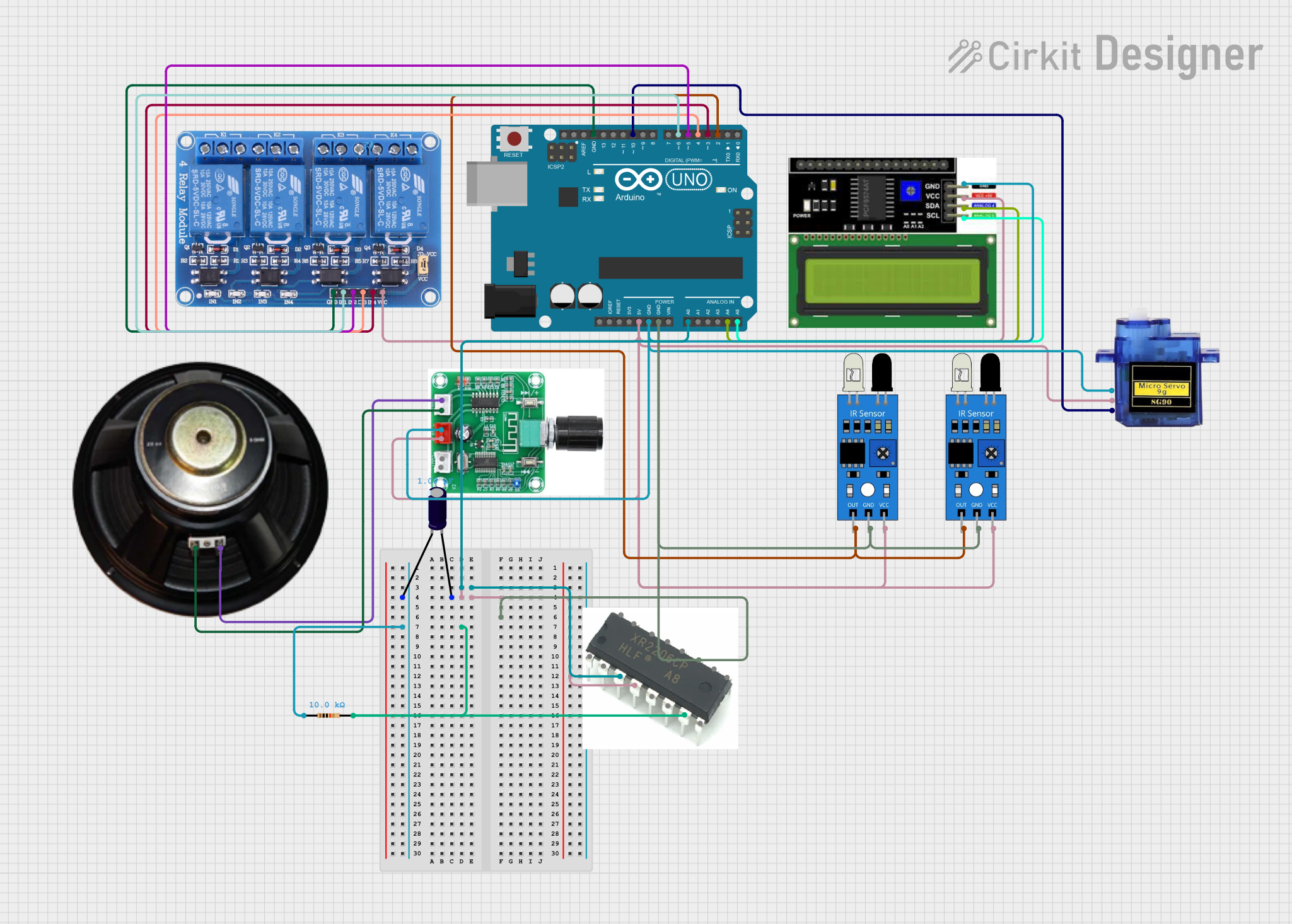
Circuit Documentation
Summary
The circuit is designed to generate sound waves controlled by a potentiometer, display frequency information on an LCD, and respond to IR sensor inputs to control a servo and relay channels. The core of the circuit is an Arduino UNO microcontroller, which interfaces with an XR2206 function generator, two IR sensors, a 4-channel relay, a servo motor, an LCD display with I2C interface, a PAM8403 audio amplifier, and a speaker. The circuit also includes a resistor and an electrolytic capacitor for signal conditioning or power stabilization.
Component List
Relay 4 Channel 5v
- Description: A 4-channel relay module capable of controlling higher power circuits.
- Pins: GND, IN1, IN2, IN3, IN4, VCC, COM1, COM2, COM3, COM4, NO1, NO2, NO3, NO4, NC1, NC2, NC3, NC4
IR Sensor
- Description: An infrared sensor for detecting proximity or motion.
- Pins: out, gnd, vcc
PAM8403
- Description: A class D audio amplifier.
- Pins: -, +
Speaker
- Description: An audio output device.
- Pins: +, -
Arduino UNO
- Description: A microcontroller board based on the ATmega328P.
- Pins: UNUSED, IOREF, Reset, 3.3V, 5V, GND, Vin, A0, A1, A2, A3, A4, A5, SCL, SDA, AREF, D13, D12, D11, D10, D9, D8, D7, D6, D5, D4, D3, D2, D1, D0
LCD I2C Display
- Description: A liquid crystal display with an I2C interface.
- Pins: GND, VCC, SDA, SCL
Micro Servo 9G
- Description: A small servo motor for precise angular movement.
- Pins: GND, +5V, PWM
XR2206 HLF 224A8
- Description: A function generator IC for creating various waveforms.
- Pins: Pin1 to Pin16
Resistor
- Description: A passive two-terminal electrical component that implements electrical resistance.
- Pins: pin1, pin2
- Properties: Resistance: 10000 Ohms
Electrolytic Capacitor
- Description: A capacitor with an electrolyte that serves as the cathode.
- Pins: -, +
- Properties: Capacitance: 0.000001 Farads
Wiring Details
Relay 4 Channel 5v
- GND: Connected to Arduino UNO GND
- IN1: Connected to Arduino UNO D6
- IN2: Connected to Arduino UNO D5
- IN3: Connected to Arduino UNO D4
- IN4: Connected to Arduino UNO D3
- VCC: Connected to Arduino UNO 5V
IR Sensor
- out: Connected to Arduino UNO D2
- gnd: Connected to Arduino UNO GND
- vcc: Connected to Arduino UNO 5V
PAM8403
- -: Connected to Speaker -
- +: Connected to Speaker +
Speaker
- +: Connected to PAM8403 +
- -: Connected to PAM8403 -
Arduino UNO
- A0: Connected to XR2206 Pin3
- 5V: Connected to VCC of various components (IR sensors, Relay, LCD, Servo, PAM8403)
- GND: Connected to GND of various components (IR sensors, Relay, LCD, Servo, PAM8403)
- D6, D5, D4, D3: Connected to Relay IN1, IN2, IN3, IN4 respectively
- A4: Connected to LCD SDA
- A5: Connected to LCD SCL
- D2: Connected to IR sensors out
- D10: Connected to Servo PWM
LCD I2C Display
- GND: Connected to Arduino UNO GND
- VCC: Connected to Arduino UNO 5V
- SDA: Connected to Arduino UNO A4
- SCL: Connected to Arduino UNO A5
Micro Servo 9G
- GND: Connected to Arduino UNO GND
- +5V: Connected to Arduino UNO 5V
- PWM: Connected to Arduino UNO D10
XR2206 HLF 224A8
- Pin3: Connected to Arduino UNO A0
- Pin4: Connected to Electrolytic Capacitor +
- Pin11: Connected to Arduino UNO GND
- Pin7: Connected to Resistor pin2
Resistor
- pin1: Connected to Electrolytic Capacitor -
- pin2: Connected to XR2206 Pin7
Electrolytic Capacitor
- -: Connected to Resistor pin1
- +: Connected to XR2206 Pin4
Documented Code
#include <Wire.h>
#include <LiquidCrystal_I2C.h>
#include <Servo.h>

// Relay pin definitions
const int relayPin1 = 6;
const int relayPin2 = 5;
const int relayPin3 = 4;
const int relayPin4 = 3;

// Potentiometer pin definition
const int potPin = A0;

// IR sensor pin definitions
const int irSensor1 = 2;
const int irSensor2 = 2;

// Servo pin definition
const int servoPin = 10;
Servo myServo;

// LCD I2C address and dimensions
LiquidCrystal_I2C lcd(0x27, 16, 2);

// Variable to store the frequency
int frequency = 100;

void setup() {
  // Initialize serial communication
  Serial.begin(9600);

  // Initialize relay pins as outputs
  pinMode(relayPin1, OUTPUT);
  pinMode(relayPin2, OUTPUT);
  pinMode(relayPin3, OUTPUT);
  pinMode(relayPin4, OUTPUT);

  // Initialize potentiometer pin as input
  pinMode(potPin, INPUT);

  // Initialize IR sensor pins as input
  pinMode(irSensor1, INPUT);
  pinMode(irSensor2, INPUT);

  // Initialize servo
  myServo.attach(servoPin);

  // Initialize LCD
  lcd.begin(16, 2);
  lcd.backlight();
  lcd.setCursor(0, 0);
  lcd.print("Soundwave Gen");
}

void loop() {
  // Read the analog value from the potentiometer
  int potValue = analogRead(potPin);

  // Map the potentiometer value to a frequency range (e.g., 20Hz to 20kHz)
  frequency = map(potValue, 0, 1023, 20, 20000);

  // Print the new frequency to the serial monitor
  Serial.print("Frequency: ");
  Serial.print(frequency);
  Serial.println(" Hz");

  // Display the frequency value on the LCD
  lcd.setCursor(0, 1);
  lcd.print("Freq: ");
  lcd.print(frequency);
  lcd.print(" Hz");

  // Control relay channels based on potentiometer value
  if (potValue > 512) {
    digitalWrite(relayPin1, HIGH);
    digitalWrite(relayPin2, LOW);
    digitalWrite(relayPin3, HIGH);
    digitalWrite(relayPin4, LOW);
  } else {
    digitalWrite(relayPin1, LOW);
    digitalWrite(relayPin2, HIGH);
    digitalWrite(relayPin3, LOW);
    digitalWrite(relayPin4, HIGH);
  }

  // Read IR sensor values
  int irValue1 = digitalRead(irSensor1);
  int irValue2 = digitalRead(irSensor2);

  // Control servo based on IR sensor values
  if (irValue1 == LOW || irValue2 == LOW) {
    myServo.write(90); // Move servo to 90 degrees
  } else {
    myServo.write(0); // Move servo to 0 degrees
  }

  // Add a small delay to avoid flickering
  delay(100);
}
This code is responsible for reading the analog value from a potentiometer connected to pin A0, mapping this value to a frequency range, and displaying it on an LCD. It also controls a set of relays and a servo motor based on the potentiometer's value and the output of two IR sensors. The relays and servo are connected to digital pins D3 to D6 and D10, respectively. The LCD uses the I2C protocol, connected to analog pins A4 and A5 for SDA and SCL lines.