ESP32-Based Light-Responsive Servo Controller
Circuit Documentation
Summary
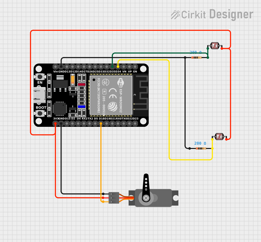
The circuit in question appears to be a light-sensing system that uses photocells (Light Dependent Resistors - LDRs) to measure light intensity and an ESP32 microcontroller to process the readings. The ESP32 then controls a servo motor based on the light intensity detected by the photocells. The circuit includes two photocells, two resistors, an ESP32 microcontroller, and a servo motor.
Component List
Photocell (LDR)
- Description: A light-sensitive device used to detect the intensity of light.
- Pins: 2 (pin 0, pin 1)
ESP32 (30 pin)
- Description: A microcontroller with Wi-Fi and Bluetooth capabilities, used for processing and controlling various functions in the circuit.
- Pins: 30 (EN, VP, VN, D34, D35, D32, D33, D25, D26, D27, D14, D12, D13, GND, Vin, D23, D22, TX0, RX0, D21, D19, D18, D5, TX2, RX2, D4, D2, D15, 3V3)
Servo
- Description: An actuator that can be precisely controlled for position, commonly used for steering mechanisms in remote-controlled vehicles, robotics, etc.
- Pins: 3 (GND, VCC, PWM)
Resistor
- Description: A passive two-terminal electrical component that implements electrical resistance as a circuit element.
- Properties: Resistance value of 200 Ohms
Wiring Details
Photocell (LDR)
- Pin 0: Connected to the ESP32 pin D35 (for the first LDR) and pin D34 (for the second LDR).
- Pin 1: Connected to the 3V3 power supply of the ESP32.
ESP32 (30 pin)
- Pin D35: Connected to the first photocell (pin 0).
- Pin D34: Connected to the second photocell (pin 0).
- Pin 3V3: Provides power to both photocells (pin 1) and the servo motor (VCC).
- Pin GND: Common ground for the resistors and the servo motor.
- Pin D18: Controls the servo motor (PWM pin).
Servo
- GND: Connected to the ESP32 GND pin.
- VCC: Powered by the ESP32 3V3 pin.
- PWM: Controlled by the ESP32 pin D18.
Resistor
- Pin 1: Connected to the ESP32 GND pin (both resistors are connected to this pin).
- Pin 2: Connected to the ESP32 pin D35 (for the first resistor) and pin D34 (for the second resistor).
Documented Code
No code was provided for the microcontroller. The expected behavior, based on the hardware configuration, would be for the ESP32 to read the voltage across the photocells, which changes with light intensity. The ESP32 would then use this information to control the position of the servo motor. However, without the actual code, we cannot document the specific functionality or logic implemented in the microcontroller.