
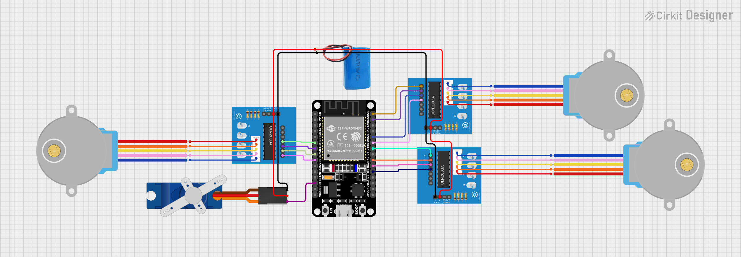
Circuit Documentation
Summary
The circuit in question is designed to control multiple stepper motors and a servo motor using an ESP32 microcontroller. The ESP32 is interfaced with three ULN2003A breakout boards, each of which is connected to a 28BYJ-48 stepper motor. Additionally, a Tower Pro SG90 servo motor is controlled directly by the ESP32. The entire circuit is powered by a 5V battery, which supplies power to the ULN2003A breakout boards and the servo motor.
Component List
ESP32 (30 pin)
- Description: A microcontroller with WiFi and Bluetooth capabilities, featuring a wide range of GPIO pins.
- Pins: EN, VP, VN, D34, D35, D32, D33, D25, D26, D27, D14, D12, D13, GND, Vin, D23, D22, TX0, RX0, D21, D19, D18, D5, TX2, RX2, D4, D2, D15, 3V3
ULN2003A Breakout Board
- Description: A breakout board for the ULN2003A, a 7-channel Darlington array used for driving stepper motors.
- Pins: In 1, In 2, In 3, In 4, In 5, In 6, In 7, 0V, +5V, ON/OFF jumper switch, BLUE wire, PINK wire, YELLOW wire, ORANGE wire, RED wire
28BYJ-48 Stepper Motor
- Description: A small, 5-wire, unipolar stepper motor commonly used for precision movement control.
- Pins: BLUE, PINK, YELLOW, ORANGE, RED
Tower Pro SG90 Servo
- Description: A small and lightweight servo motor suitable for projects that require precise position control.
- Pins: Signal, +5V, GND
5V Battery
- Description: A power source used to supply 5V to the circuit.
- Pins: positive, negative
Wiring Details
ESP32 (30 pin)
- D32 -> ULN2003A breakout board (In 4)
- D33 -> ULN2003A breakout board (In 3)
- D25 -> ULN2003A breakout board (In 2)
- D26 -> ULN2003A breakout board (In 1)
- D13 -> Tower Pro SG90 servo (Signal)
- D23 -> ULN2003A breakout board (In 1)
- D22 -> ULN2003A breakout board (In 2)
- D21 -> ULN2003A breakout board (In 3)
- D19 -> ULN2003A breakout board (In 4)
- D18 -> ULN2003A breakout board (In 1)
- TX2 -> ULN2003A breakout board (In 2)
- RX2 -> ULN2003A breakout board (In 3)
- D4 -> ULN2003A breakout board (In 4)
ULN2003A Breakout Board
- In 1 -> ESP32 (D26, D23, D18)
- In 2 -> ESP32 (D25, D22, TX2)
- In 3 -> ESP32 (D33, D21, RX2)
- In 4 -> ESP32 (D32, D19, D4)
- 0V -> 5V Battery (negative)
- +5V -> 5V Battery (positive)
- BLUE wire -> 28BYJ-48 Stepper Motor (BLUE)
- PINK wire -> 28BYJ-48 Stepper Motor (PINK)
- YELLOW wire -> 28BYJ-48 Stepper Motor (YELLOW)
- ORANGE wire -> 28BYJ-48 Stepper Motor (ORANGE)
- RED wire -> 28BYJ-48 Stepper Motor (RED)
28BYJ-48 Stepper Motor
- BLUE -> ULN2003A breakout board (BLUE wire)
- PINK -> ULN2003A breakout board (PINK wire)
- YELLOW -> ULN2003A breakout board (YELLOW wire)
- ORANGE -> ULN2003A breakout board (ORANGE wire)
- RED -> ULN2003A breakout board (RED wire)
Tower Pro SG90 Servo
- Signal -> ESP32 (D13)
- +5V -> 5V Battery (positive)
- GND -> 5V Battery (negative)
5V Battery
- positive -> ULN2003A breakout board (+5V), Tower Pro SG90 servo (+5V)
- negative -> ULN2003A breakout board (0V), Tower Pro SG90 servo (GND)
Documented Code
No code was provided for the microcontroller(s) in the circuit. The documentation of the code would typically include descriptions of the functions, the main loop, and any interrupt service routines, along with comments explaining the logic and purpose of each section of the code. Since no code is available, this section cannot be completed.