
Arduino UNO and ESP8266 NodeMCU Interactive Display with Pushbutton Inputs and Audio Feedback
View and Edit Project In Cirkit Designer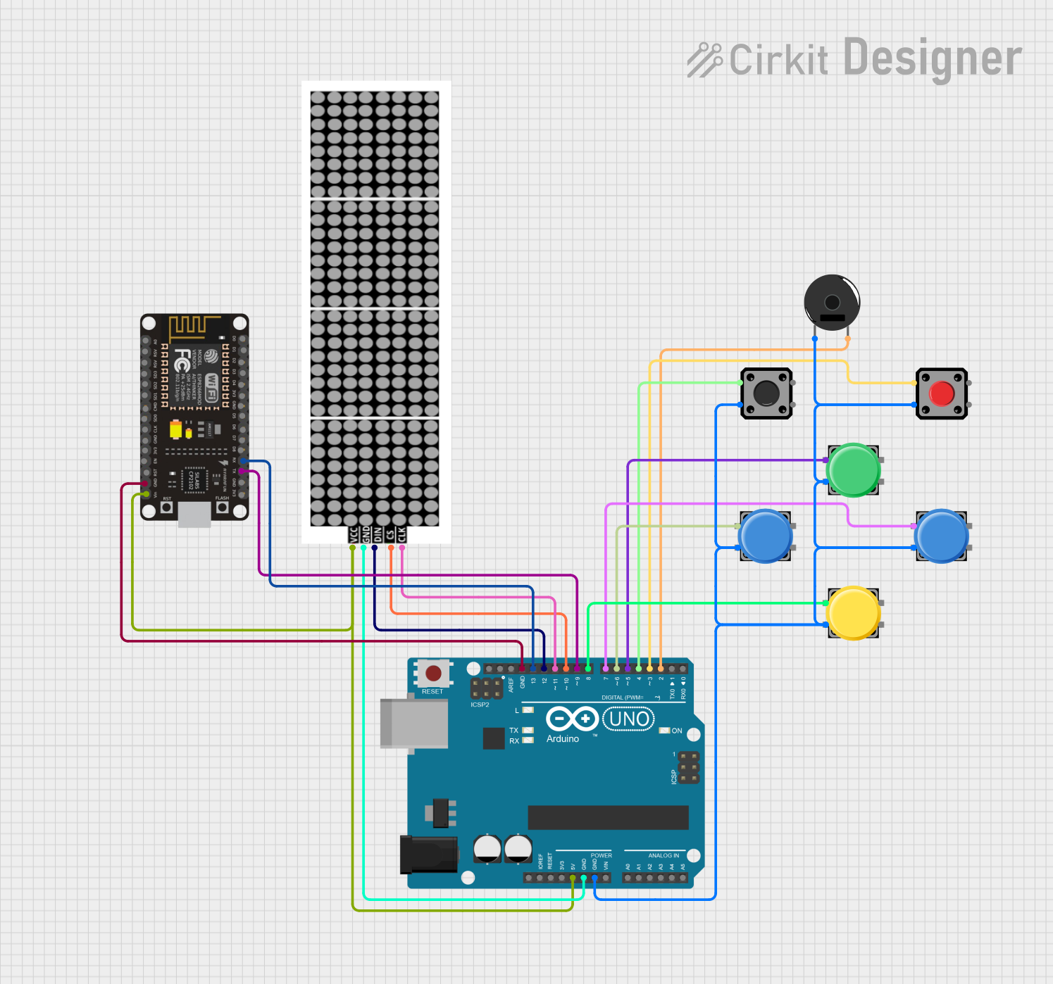
Circuit Documentation
Summary
This document provides a detailed overview of a circuit that includes various pushbuttons, a piezo buzzer, an LED dot display, an Arduino UNO microcontroller, and an ESP8266 NodeMCU microcontroller. The circuit is designed to interface with these components, allowing for input from the pushbuttons, output to the piezo buzzer and LED dot display, and communication between the Arduino UNO and the ESP8266 NodeMCU.
Component List
Pushbutton
- Description: A simple switch mechanism for control of a machine or electrical device.
- Pins: Pin 1, Pin 2, Pin 3, Pin 4
Tactile Switch Buttons - 12mm Square
- Description: A momentary pushbutton switch that provides tactile feedback.
- Pins: 1, 2, 3, 4
Piezo Buzzer
- Description: An electronic device that emits a tone when an electric current is passed through it.
- Pins: pin 1, pin 2
Arduino UNO
- Description: A microcontroller board based on the ATmega328P.
- Pins: UNUSED, IOREF, Reset, 3.3V, 5V, GND, Vin, A0, A1, A2, A3, A4, A5, SCL, SDA, AREF, D13, D12, D11, D10, D9, D8, D7, D6, D5, D4, D3, D2, D1, D0
LED DOT DISPLAY
- Description: An array of LEDs arranged in a matrix to display information.
- Pins: VCC, GND, DIN, CS, CLK
ESP8266 NodeMCU
- Description: A low-cost Wi-Fi microchip with full TCP/IP stack and microcontroller capability.
- Pins: D0, D1, D2, D3, D4, 3V3, GND, D5, D6, D7, D8, RX, TX, A0, RSV, SD3, SD2, SD1, CMD, SD0, CLK, EN, RST, VIN
Wiring Details
Pushbutton
- Pin 1: Connected to GND of Arduino UNO.
- Pin 3: Connected to digital pins (D3, D5, D6, D7, D8) of Arduino UNO depending on the instance.
- Pin 4: Connected to digital pin D3 of Arduino UNO for one instance.
Tactile Switch Buttons - 12mm Square
- Pin 1: Connected to GND of Arduino UNO.
- Pin 2: Connected to digital pin D4 of Arduino UNO.
Piezo Buzzer
- Pin 1: Connected to GND of Arduino UNO.
- Pin 2: Connected to digital pin D2 of Arduino UNO.
Arduino UNO
- 5V: Connected to VIN of ESP8266 NodeMCU and VCC of LED DOT DISPLAY.
- GND: Connected to GND of ESP8266 NodeMCU, GND of LED DOT DISPLAY, and pin 1 of Piezo Buzzer.
- D2 to D8: Connected to various pushbuttons as detailed above.
- D9: Connected to TX of ESP8266 NodeMCU.
- D10: Connected to CS of LED DOT DISPLAY.
- D11: Connected to CLK of LED DOT DISPLAY.
- D12: Connected to DIN of LED DOT DISPLAY.
- D13: Connected to RX of ESP8266 NodeMCU.
LED DOT DISPLAY
- VCC: Connected to 5V of Arduino UNO.
- GND: Connected to GND of Arduino UNO.
- DIN: Connected to digital pin D12 of Arduino UNO.
- CS: Connected to digital pin D10 of Arduino UNO.
- CLK: Connected to digital pin D11 of Arduino UNO.
ESP8266 NodeMCU
- VIN: Connected to 5V of Arduino UNO.
- GND: Connected to GND of Arduino UNO.
- RX: Connected to digital pin D13 of Arduino UNO.
- TX: Connected to digital pin D9 of Arduino UNO.
Documented Code
Arduino UNO Code (sketch.ino)
void setup() {
  // put your setup code here, to run once:

}

void loop() {
  // put your main code here, to run repeatedly:

}
ESP8266 NodeMCU Code
No code provided for the ESP8266 NodeMCU in the input data.
This documentation provides an initial framework for understanding the circuit's design and functionality. Further details, such as the specific behavior of the microcontroller code and the interaction between components, would be added as the design and implementation progress.