
Bluetooth-Controlled LED Lighting System with Arduino Mega and 4-Channel Relay
View and Edit Project In Cirkit Designer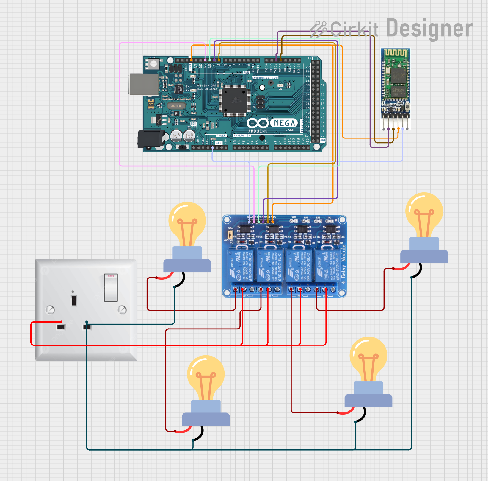
Circuit Documentation
Summary
This circuit is designed to control four AC-powered LED bulbs using a 4-channel relay module. The relays are actuated by an Arduino Mega 2560 microcontroller, which receives commands via a Bluetooth module. The circuit allows for individual control of each LED bulb, enabling them to be switched on or off remotely. The AC wall plug point provides the main power source for the LED bulbs, while the Arduino and Bluetooth module are powered by a 5V supply.
Component List
LED Bulb AC / Bombillo AC
- Quantity: 4
- Description: These are AC-powered LED bulbs that can be turned on or off by the relay module.
- Pins:
+(Positive),-(Negative)
Relay 4 Channel 5v
- Quantity: 1
- Description: A 4-channel relay module that switches the LED bulbs on and off. It is controlled by the Arduino Mega 2560.
- Pins:
GND,IN1,IN2,IN3,IN4,VCC,COM1,COM2,COM3,COM4,NO1,NO2,NO3,NO4,NC1,NC2,NC3,NC4
Arduino Mega 2560
- Quantity: 1
- Description: The main microcontroller unit that controls the relay module and communicates with the Bluetooth module.
- Pins: Multiple digital and analog pins, including
GND,5V,D8 PWM,D9 PWM,D10 PWM,D11 PWM,D17 PWM/RX2,D16 PWM/TX2, and others.
Bluetooth Module
- Quantity: 1
- Description: A Bluetooth module used for wireless communication with the Arduino Mega 2560.
- Pins:
en,vcc,gnd,txd,rxd,state
AC Wall Plug Point
- Quantity: 1
- Description: Provides the main AC power source for the LED bulbs.
- Pins:
E(Earth),N(Neutral),L(Live)
Wiring Details
LED Bulb AC / Bombillo AC
- Positive Pin (
+): Connected to theNOxpin of the Relay 4 Channel 5v module, wherexis the relay number (1 to 4). - Negative Pin (
-): Connected to theLpin of the AC wall plug point.
Relay 4 Channel 5v
- Ground (
GND): Connected to theGNDpin of the Arduino Mega 2560 and thegndpin of the Bluetooth module. - Input Pins (
IN1,IN2,IN3,IN4): Each connected to a corresponding PWM pin on the Arduino Mega 2560 (D8 PWM,D9 PWM,D10 PWM,D11 PWM). - Voltage Supply (
VCC): Connected to the5Vpin of the Arduino Mega 2560 and thevccpin of the Bluetooth module. - Common Pins (
COM1,COM2,COM3,COM4): All connected to theNpin of the AC wall plug point. - Normally Open Pins (
NO1,NO2,NO3,NO4): Each connected to the positive pin (+) of a corresponding LED bulb.
Arduino Mega 2560
- Ground (
GND): Connected to theGNDpin of the Relay 4 Channel 5v and thegndpin of the Bluetooth module. - 5V Output (
5V): Connected to theVCCpin of the Relay 4 Channel 5v and thevccpin of the Bluetooth module. - PWM Pins (
D8 PWM,D9 PWM,D10 PWM,D11 PWM): Each connected to a corresponding input pin on the Relay 4 Channel 5v (IN1,IN2,IN3,IN4). - Serial Communication Pins (
D17 PWM/RX2,D16 PWM/TX2):D17 PWM/RX2connected to thetxdpin of the Bluetooth module, andD16 PWM/TX2connected to therxdpin of the Bluetooth module.
Bluetooth Module
- Ground (
gnd): Connected to theGNDpin of the Arduino Mega 2560. - Voltage Supply (
vcc): Connected to the5Vpin of the Arduino Mega 2560. - Transmit (
txd): Connected to theD17 PWM/RX2pin of the Arduino Mega 2560. - Receive (
rxd): Connected to theD16 PWM/TX2pin of the Arduino Mega 2560.
AC Wall Plug Point
- Neutral (
N): Connected to the common pins (COM1,COM2,COM3,COM4) of the Relay 4 Channel 5v. - Live (
L): Connected to the negative pins (-) of all LED bulbs.
Documented Code
/*
 * This Arduino sketch controls a 4-channel relay module to switch on and off
 * four LED bulbs. The relays are controlled via PWM pins on the Arduino Mega
 * 2560. A Bluetooth module is used for communication to receive commands for
 * controlling the relays.
 */

// Pin definitions
const int relay1 = 8;  // Relay 1 connected to D8
const int relay2 = 9;  // Relay 2 connected to D9
const int relay3 = 10; // Relay 3 connected to D10
const int relay4 = 11; // Relay 4 connected to D11

void setup() {
  // Initialize serial communication for Bluetooth
  Serial2.begin(9600);

  // Initialize relay pins as outputs
  pinMode(relay1, OUTPUT);
  pinMode(relay2, OUTPUT);
  pinMode(relay3, OUTPUT);
  pinMode(relay4, OUTPUT);

  // Turn off all relays initially
  digitalWrite(relay1, LOW);
  digitalWrite(relay2, LOW);
  digitalWrite(relay3, LOW);
  digitalWrite(relay4, LOW);
}

void loop() {
  // Check if data is available from Bluetooth
  if (Serial2.available()) {
    char command = Serial2.read();

    // Control relays based on received command
    switch (command) {
      case '1':
        digitalWrite(relay1, HIGH); // Turn on Relay 1
        break;
      case '2':
        digitalWrite(relay1, LOW);  // Turn off Relay 1
        break;
      case '3':
        digitalWrite(relay2, HIGH); // Turn on Relay 2
        break;
      case '4':
        digitalWrite(relay2, LOW);  // Turn off Relay 2
        break;
      case '5':
        digitalWrite(relay3, HIGH); // Turn on Relay 3
        break;
      case '6':
        digitalWrite(relay3, LOW);  // Turn off Relay 3
        break;
      case '7':
        digitalWrite(relay4, HIGH); // Turn on Relay 4
        break;
      case '8':
        digitalWrite(relay4, LOW);  // Turn off Relay 4
        break;
      default:
        // Do nothing for unrecognized commands
        break;
    }
  }
}
This code is responsible for initializing the Arduino Mega 2560's pins connected to the relay module and setting up serial communication with the Bluetooth module. The loop function listens for commands from the Bluetooth module and controls the state of the relays accordingly. Each relay corresponds to one LED bulb, allowing individual control of each bulb's power state.